
Energy based partial circumferential hemorrhoid repair device

a technology of partial circumferential hemorrhoid and repair device, which is applied in the field of energy-based devices for cutting and sealing hemorrhoid tissue, can solve the problems of additional injury to the vein, venous blood collection and distension of veins, and chronic strain damage to the valve located within the vein, so as to improve the visibility of hemorrhoid tissue

Active Publication Date: 2006-02-02
TYCO HEALTHCARE GRP LP
View PDF51 Cites 43 Cited by
  • Summary
  • Abstract
  • Description
  • Claims
  • Application Information

AI Technical Summary

Benefits of technology

[0016] The present disclosure provides a novel energy based partial circumferential hemorrhoid repair device which allows improved visibility of hemorrhoid tissue entering and being sealed by the device. The device of the present disclosure obviates the need for purse string placement, since hemorrhoid tissue may be drawn into the device through standard graspers, or by surrounding the hemorrhoid tissue within the hemorrhoid repair device assembly. The configuration of the energy based partial circumferential hemorrhoid repair device permits removal of individual hemorrhoids or specific regions, instead of the entire circumference. It is, however, contemplated that the partial circumferential hemorrhoid repair device may also be rotated, while in place, to remove hemorrhoid tissue about a full circumference.

Problems solved by technology

Chronic straining damages the valves located within the veins, and venous blood collects and distends the veins to many times the normal size.
The slow flow of blood within the vein can cause additional injury to the vein, as well as thrombosis.
While rarely fatal, hemorrhoids are often painful.
This method is commonly avoided, since the procedure is thought to be difficult to perform, bloody, and susceptible to complications.
One limitation of the procedure is the depth that the circular stapler can be placed into the anus.
An additional limitation of the procedure is the amount of hemorrhoidal tissue that can be drawn into the stapling end effector of a conventional circular stapling instrument.
At present, there are no known surgical instruments that can meet all of the needs outlined above.

Method used


Image

  • Energy based partial circumferential hemorrhoid repair device
  • Energy based partial circumferential hemorrhoid repair device
  • Energy based partial circumferential hemorrhoid repair device

Examples


Embodiment Construction

[0035] Embodiments of the presently disclosed energy based partial circumferential hemorrhoid repair device will now be described in detail with reference to the figures, in which like reference numerals identify corresponding elements throughout the several views.

[0036] In the description that follows, as is traditional, the term “proximal” will refer to the end of the surgical instrument closest to the operator and the term “distal” will refer to the end of the surgical instrument furthest from the operator.

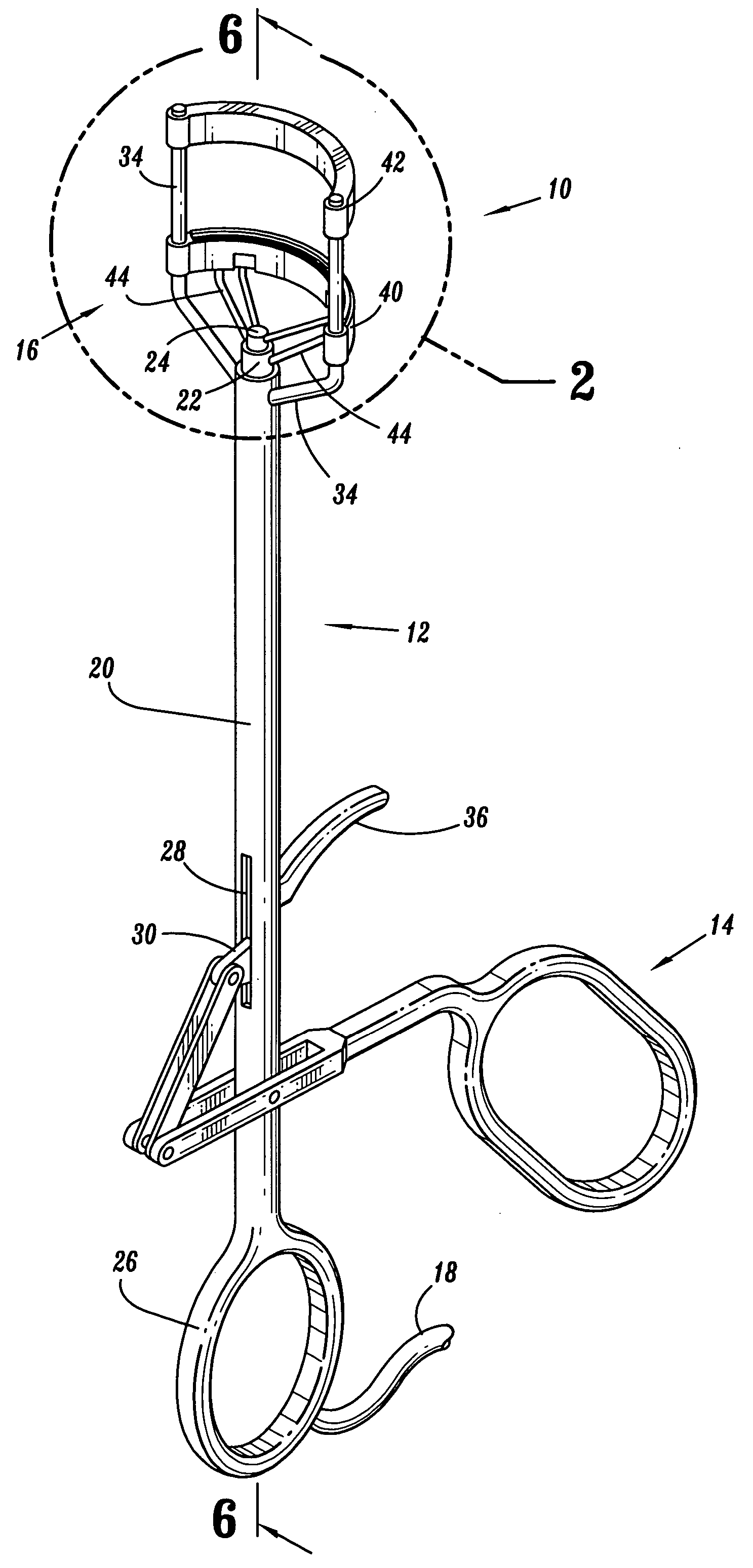
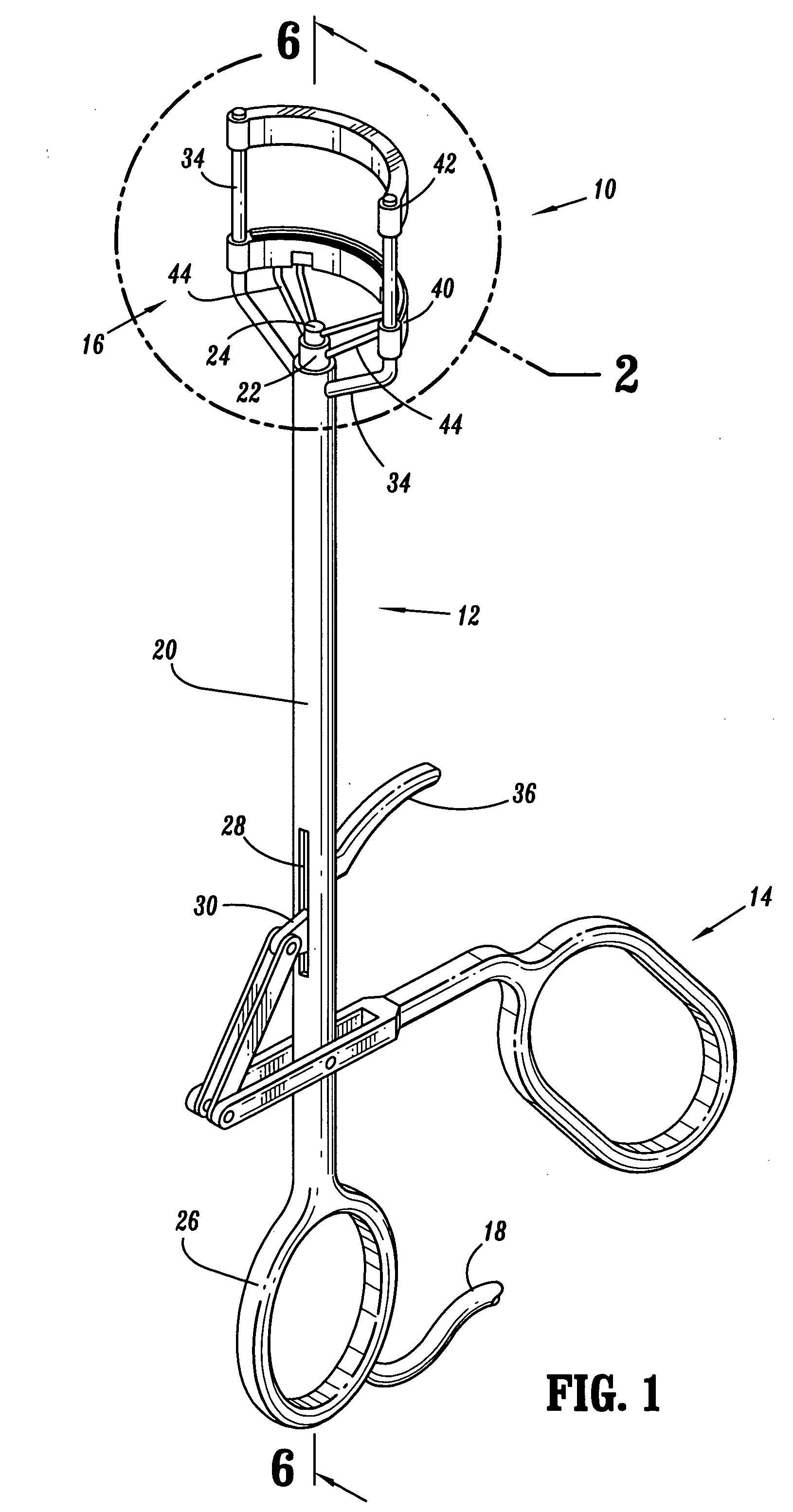
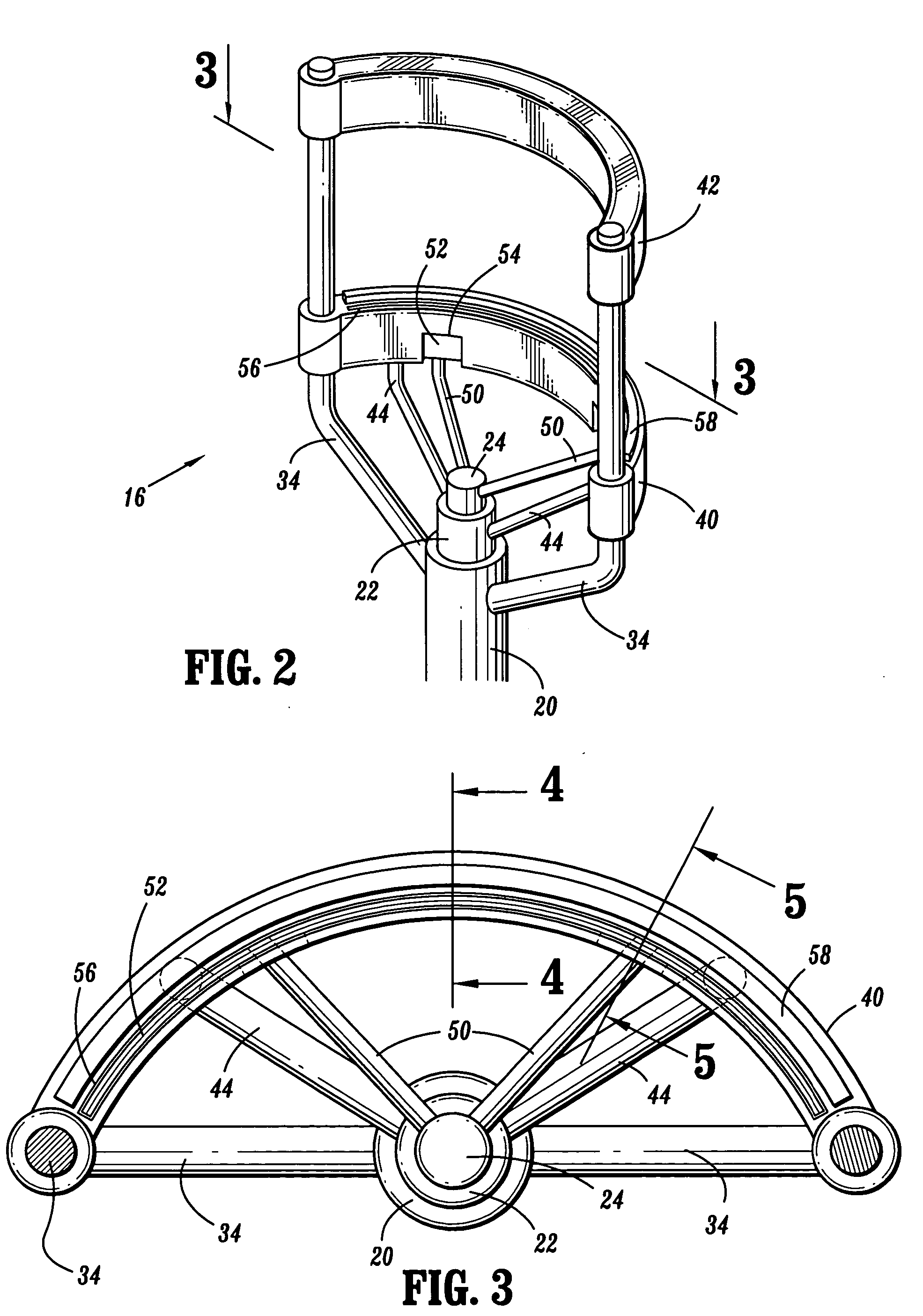
[0037] An energy based partial circumferential hemorrhoid repair device, shown generally as reference numeral 10 in FIG. 1, includes a generally tubular portion 12 having an actuator assembly 14 on a proximal end thereof and an energy based partial circumferential hemorrhoid repair device head assembly 16 on a distal end thereof. Energy based repair device 10 also includes an electrical cord 18 extending from a proximal end of actuator assembly 14 and is further connected to ...


PUM


Abstract

An energy based partial circumferential hemorrhoid repair device including an actuator assembly, and an energy based partial circumferential hemorrhoid repair device head assembly operatively connected to the actuator assembly, wherein the head assembly includes a proximal electrode assembly and a distal electrode assembly, and further wherein at least one of the electrode assemblies includes an electrode mounted thereon to facilitate sealing of hemorrhoid tissue as the two electrode assemblies are approximated.

Description

BACKGROUND [0001] 1. Field of the Disclosure [0002] The present disclosure relates to an instrument for use in treating hemorrhoids, and more particularly to an energy based device for cutting and sealing hemorrhoid tissue. [0003] 2. Background of Related Art [0004] Hemorrhoids are a swollen twisted mass of varicose veins that are located just inside the anus. Hemorrhoids are caused by chronic straining from, for example, constipation and childbirth. Chronic straining damages the valves located within the veins, and venous blood collects and distends the veins to many times the normal size. The slow flow of blood within the vein can cause additional injury to the vein, as well as thrombosis. As the patient ages, the elasticity of the tissue of the anus changes and the hemorrhoidal condition can worsen causing prolapse and anal bleeding. While rarely fatal, hemorrhoids are often painful. Treatments can range from heat packs and bed rest (in mild cases), to surgery (in extreme cases)....

Claims


Application Information

Patent Timeline
IPC IPC(8): A61B18/14
CPCA61B18/1442A61B2018/145A61B2018/0063A61B2018/005
Inventor HEINRICH, RUSSELLCUNNINGHAM, SCOTTHELFRICH, PATRICKNOLAN, TIM
Owner TYCO HEALTHCARE GRP LP
Learn More