
Method and system for setting up hosting environments in safety

a hosting environment and safety technology, applied in the direction of digital transmission, program/content distribution protection, instruments, etc., can solve the problems of aborting the booting process and long total time for verifying the e-signatures of all parts, and achieve the effect of preserving security and speeding up the setup of the hosting environmen

Inactive Publication Date: 2006-02-02
HITACHI LTD
View PDF13 Cites 40 Cited by
  • Summary
  • Abstract
  • Description
  • Claims
  • Application Information

AI Technical Summary

Benefits of technology

[0007] An object of the present invention is to provide a method for setting up hosting environments safely and quickly in building a business application system and its hosting environments by loading boot images to computer resources, using a network boot technique or the like.
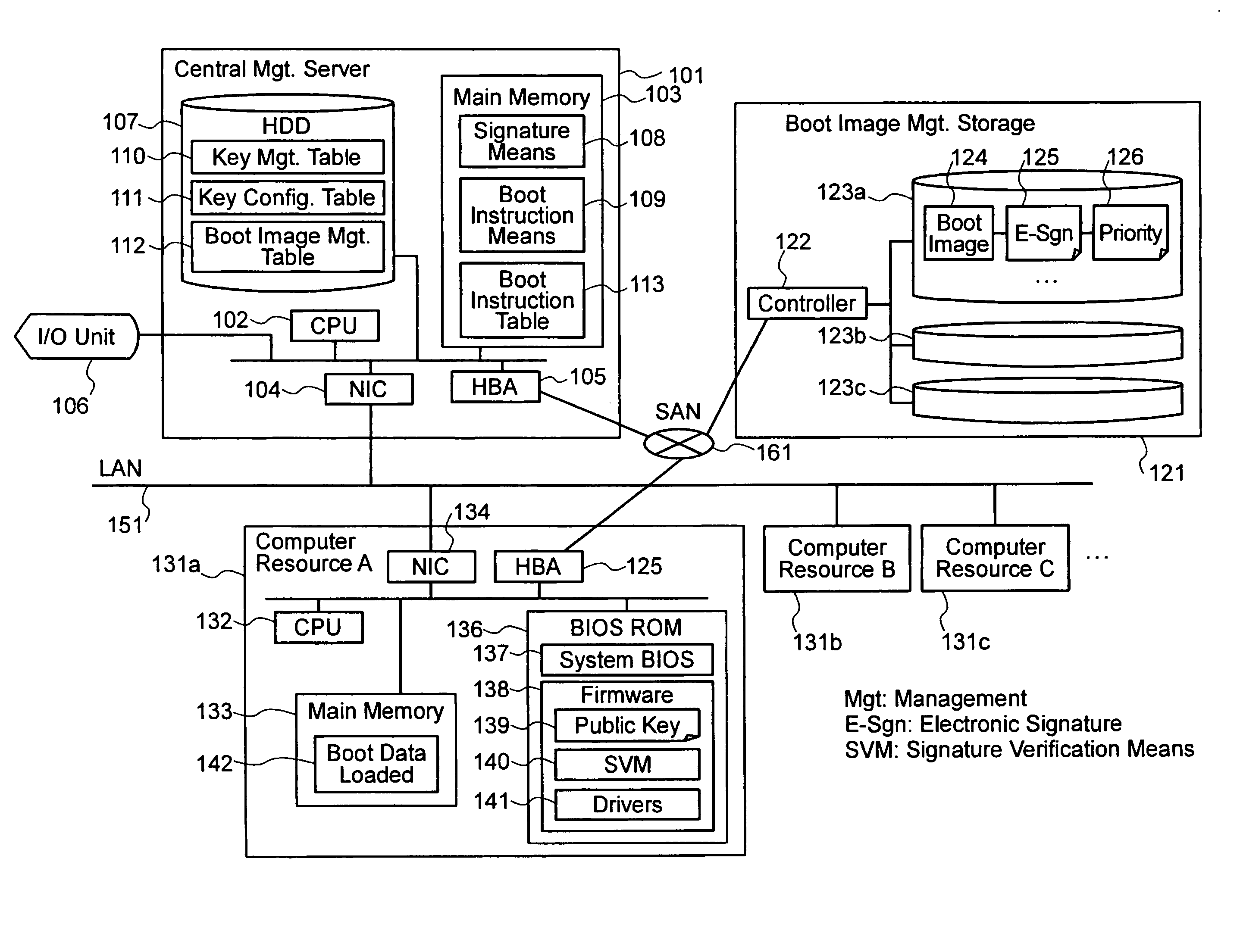
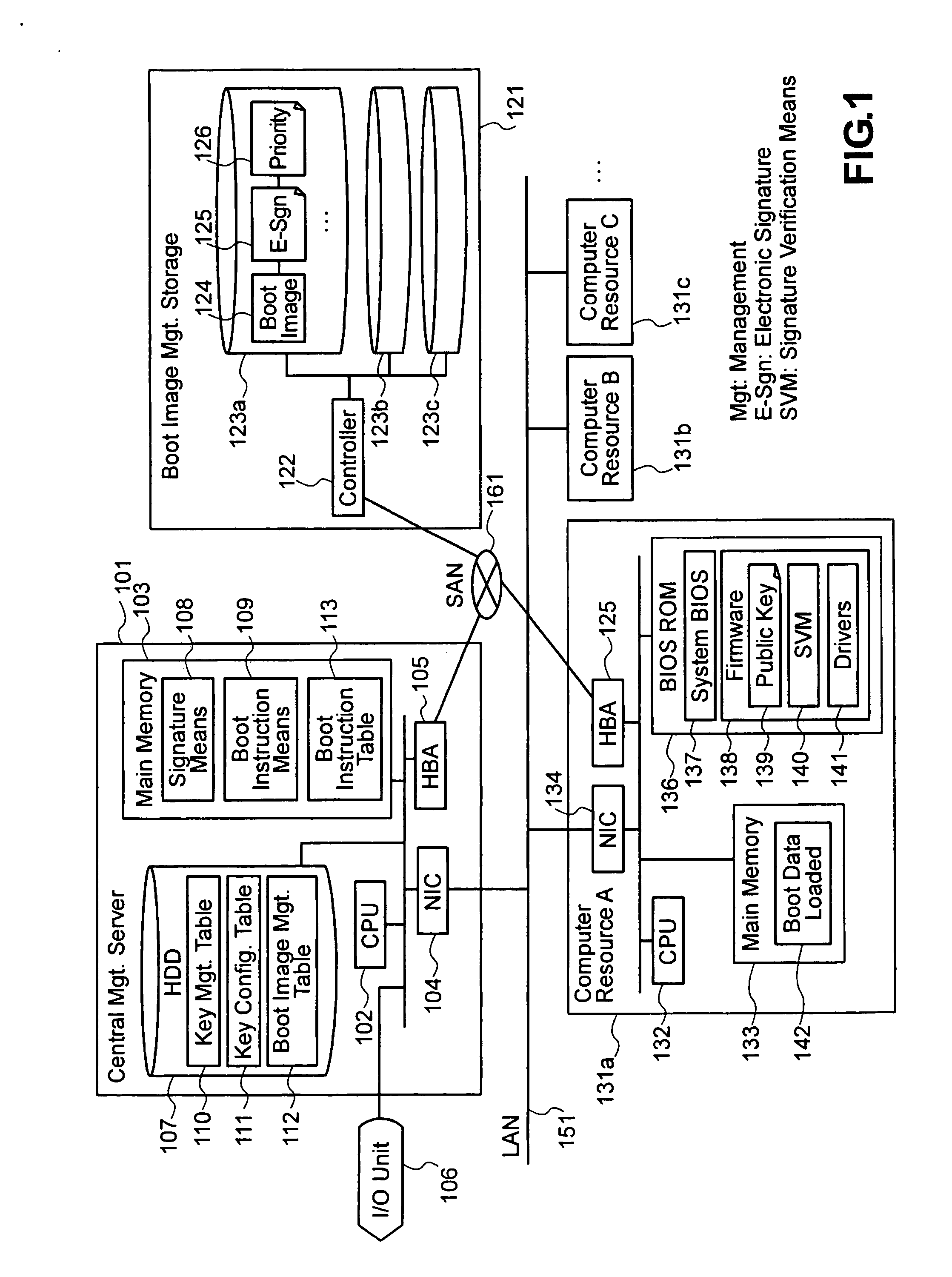
[0011] In the method for setting up hosting environments of the present invention, computer resources are booted with boot images with e-signatures loaded thereto, while verifying the e-signatures, thereby security is preserved and faster hosting environment setup can be performed.

Problems solved by technology

If the verification is successful, the computer resource executes the booting process; if the verification is unsuccessful, the computer resource does not execute the booting process.
In the middle of the booting process, if an unsuccessful verification of the e-signature of a part occurs, the booting process is aborted.
However, a total time for verifying the e-signatures of all parts may be still long.

Method used


Image

  • Method and system for setting up hosting environments in safety
  • Method and system for setting up hosting environments in safety
  • Method and system for setting up hosting environments in safety

Examples


embodiment 1

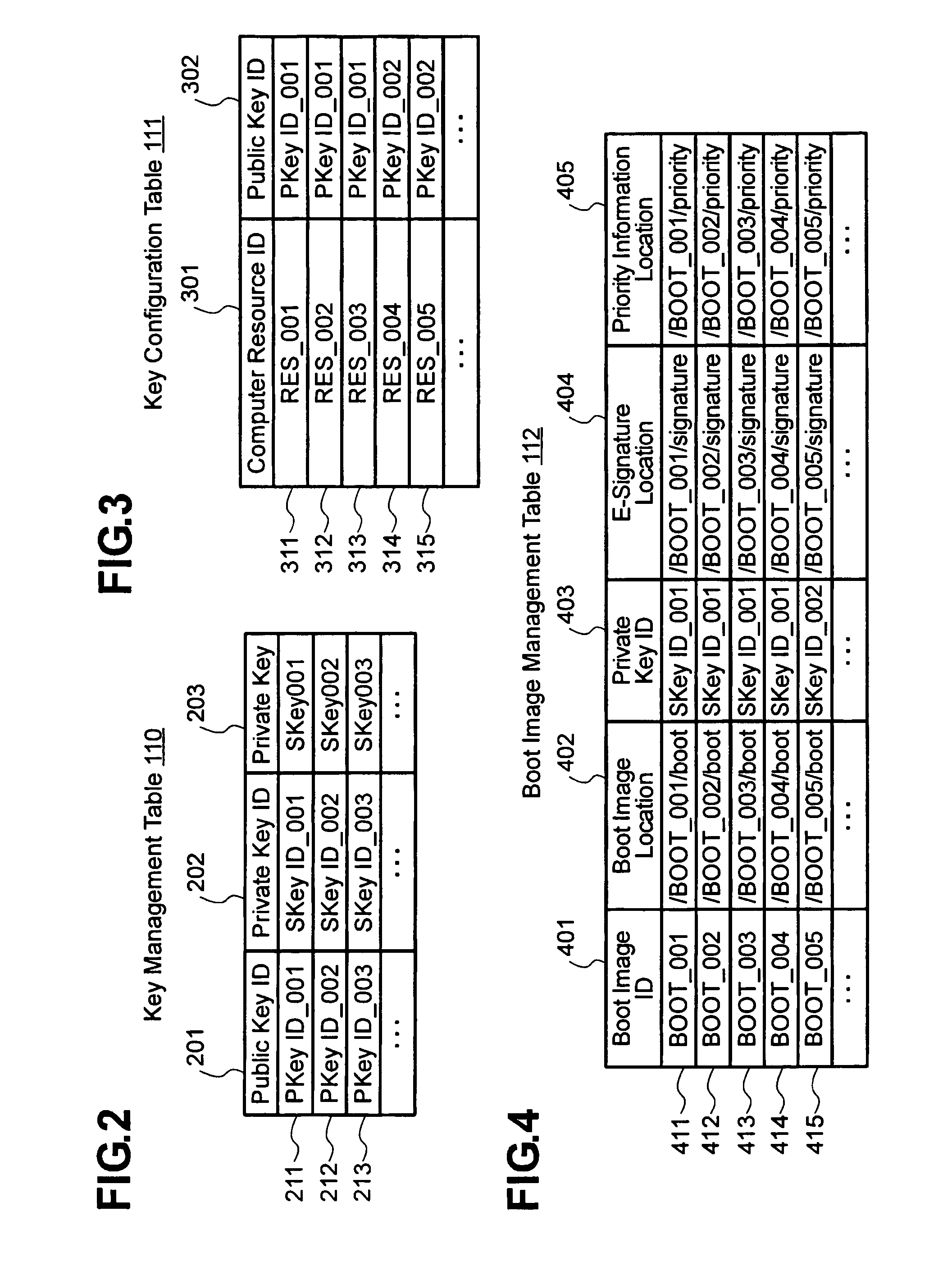
[0025] Embodiment 1 of the method for setting up hosting environments according to the present invention will be described in detail hereinafter with reference to FIGS. 1 through 8. Embodiment 1 of the present invention, which will be described hereinafter, is an example of the method in which a computer resource reads a boot image immediately before starting the booting process and verifies the e-signature with the public key held in the computer resource, wherein the boot image is divided into multiple parts, to each of which an e-signature is attached, for the purpose of solving the problem that it takes long to verify the e-signature of a large boot image. During the booting process, each part's e-signature is verified separately and, upon the detection of a part for which the verification is unsuccessful, the booting process is aborted. It is assumed that pairs of asymmetric keys (pairs of public and private keys) are prepared beforehand and the public keys are respectively sto...

embodiment 2

[0063] Embodiment 2 of a dynamic system reconfiguration method according to the present invention will be described in detail, referring to mainly FIGS. 9 through 11. Embodiment 2 of the present invention, which will be described hereinafter, is the method in which an e-signature is dynamically attached to a boot image during the booting process for hosting environment setup.

[0064]FIG. 9 shows an example of architecture to realize the method for setting up hosting environments according to Embodiment 2, involving the structure and functional blocks of the central management server, the structure and functional blocks of one of the computer resources which are controlled by the central management server, and the structure and functional blocks of the boot image management storage which stores and manages boot images. Difference from FIG. 1 used in describing Embodiment 1 lies in that a signature means 901, key management table 110, key configuration table 111, and boot image managem...


PUM


Abstract

In a data center architecture or the like, the present invention provides a method for setting up hosting environments concurrently by loading a boot image by means of network boot or the like, allowing for fast booting even with a large boot image, while preserving security. A boot image is divided into a plurality of parts. Computer resources have their public keys stored in their BIOS ROMs and e-signatures are attached to the boot image parts with a private key corresponding to one of the public keys. Also, priority levels in e-signature verification are assigned to the boot image parts. A boot instruction includes priority level setting. Only for boot image parts with that priority level or higher, e-signature verification is performed. By this manner, booting can be performed faster than booting involving verification of the e-signature to a whole boot image.

Description

CROSS-REFERENCES TO RELATED APPLICATIONS [0001] The present application is related to and claims priority from Japanese Patent Application No. 2004-218044, filed Jul. 27, 2004, and is hereby incorporated by reference for all purposes. BACKGROUND OF THE INVENTION [0002] The present invention appertains to a provisioning technique to set up hosting environments for a business application system through a data center, intra-corporate computing center, and the like. [0003] Recently, there is a move to have centralized configuration of a business application system in the architecture of a data center, intra-corporate computing center, and the like in order to make effective use of computer resources. So far, most of business application systems have been built by fixed allocation of compute resources. Instead, the above configuration builds a bushiness application system by allocating a required quantity of computer resources for a period during which the system is needed, aiming to eff...

Claims


Application Information

Patent Timeline
Patent Type & Authority Applications(United States)
IPC IPC(8): H04L9/00G06F21/12
CPCG06F21/575
Inventor KUDO, YUTAKAHAGA, FUTOSHIISHIZAKI, TAKESHI
Owner HITACHI LTD
Learn More