Eureka AIR delivers breakthrough ideas for toughest innovation challenges, trusted by R&D personnel around the world.

Non-linear spring system

Inactive Publication Date: 2006-02-09
BARNES GROUP
View PDF16 Cites 19 Cited by
  • Summary
  • Abstract
  • Description
  • Claims
  • Application Information

AI Technical Summary

Benefits of technology

[0007] The present invention provides an improved spring system which overcomes the above referred-to difficulties and others with regard to spring systems heretofore available. The spring system in accordance with the invention is particularly adapted for lifting or pivoting one component relative to another component at a controlled rate. In accordance with one embodiment of the invention, the spring system provides a lift mechanism for hinged covers, hatches and the like. In accordance with another and / or alternative embodiment of the invention, the spring system provides a lift mechanism for a vehicle hood. In accordance with still another and / or alternative embodiment of the invention, the spring system applies a non-linear force during the expansion and / or compression of the spring system. In accordance with yet another and / or alternative embodiment of the invention, the spring system is able to support significant loads while maintaining strength over a greater number of operating cycles. In accordance with still yet another and / or alternative embodiment of the invention, the spring system provides a mechanical assembly that can yield controllable forces over a long period of use and control the spring forces during extension and / or compression of the spring system. In accordance with a further and / or alternative embodiment of the invention, the one or more springs control the rate at which the spring system expands and / or contracts.

Problems solved by technology

Consequently, because these products contain a gas and / or fluid, they are subject to premature failure, due to the leakage of the gas or fluid over time.
The leakage results in a loss of control forces and a subsequent loss of spring life.

Method used


Image

  • Non-linear spring system
  • Non-linear spring system
  • Non-linear spring system

Examples


Embodiment Construction

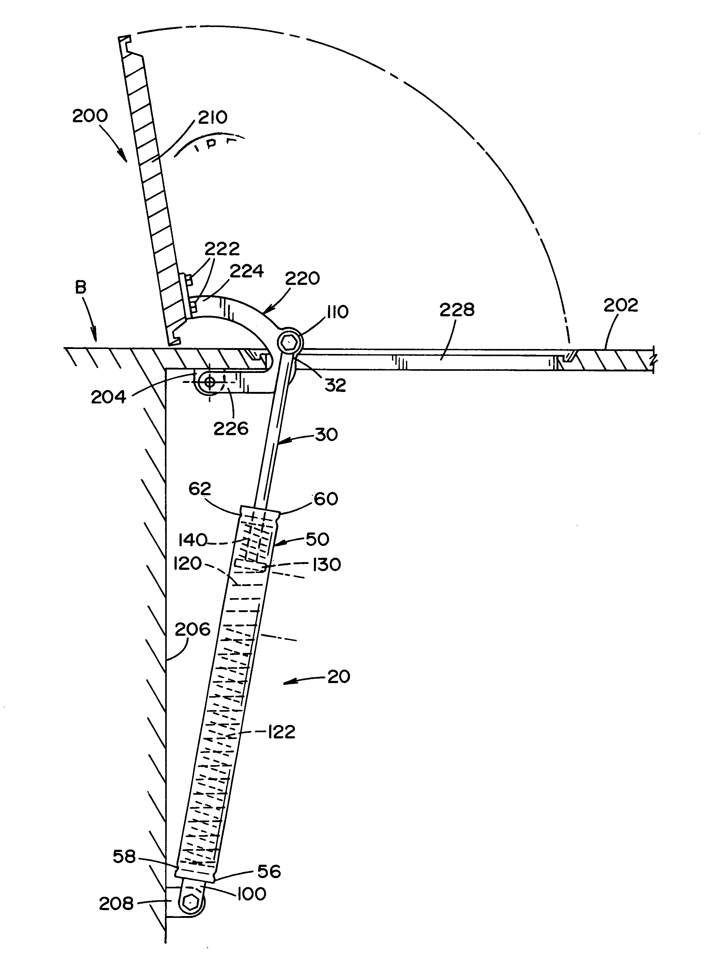
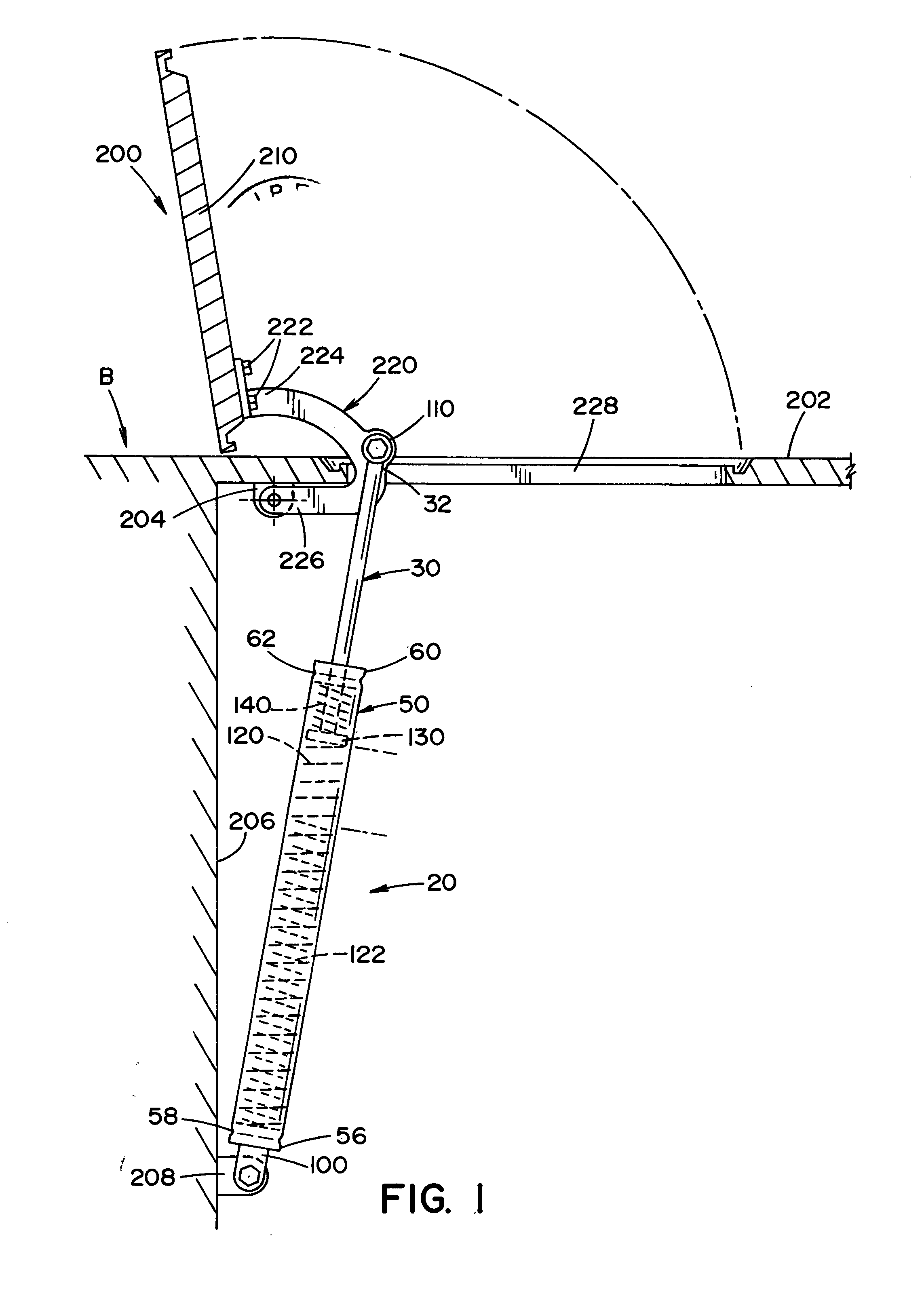
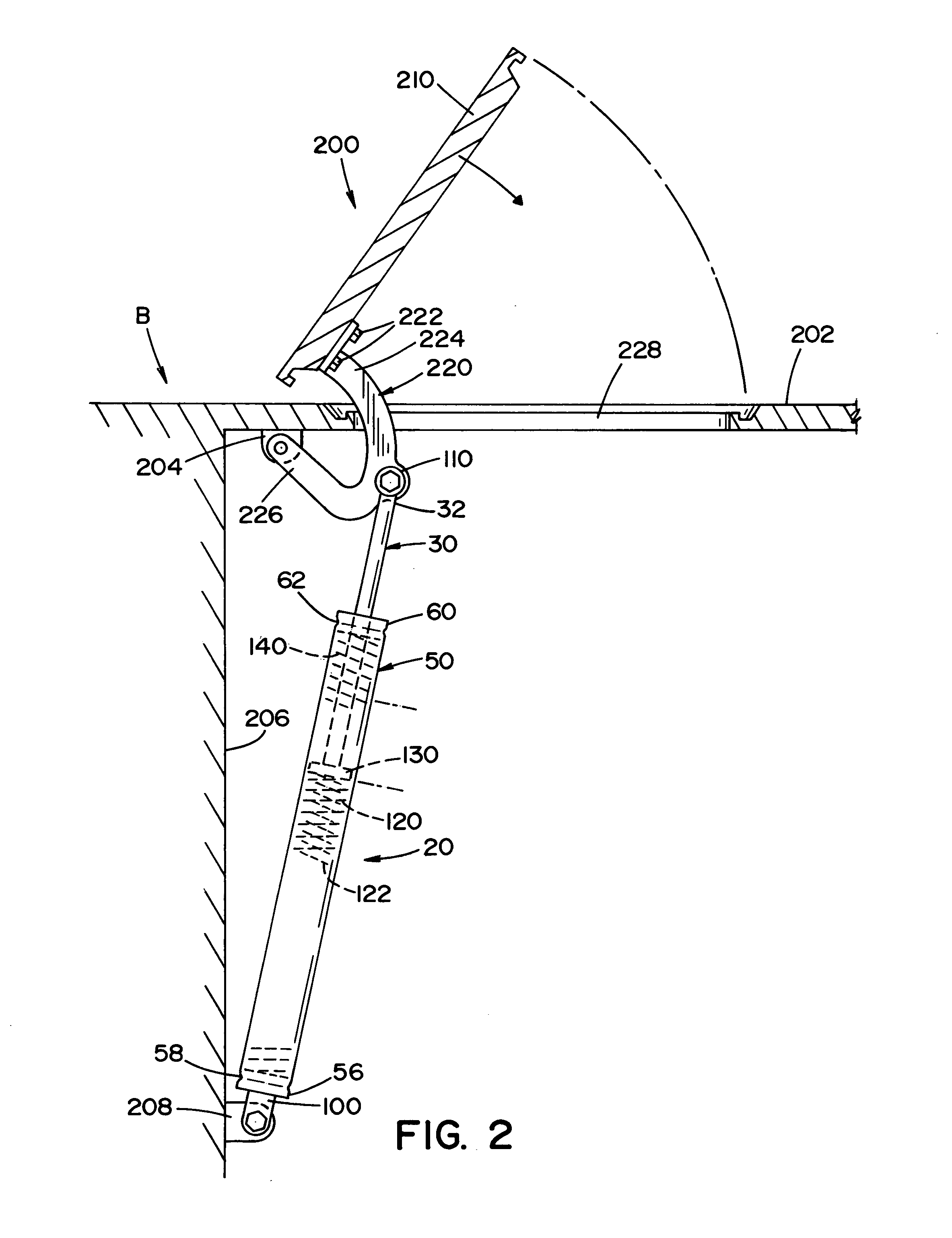
[0040] Referring now in greater detail to the drawings, wherein the showings are for the purpose of illustrating various embodiments of the invention only, and not for the purpose of limiting the invention, a spring system 20, in accordance with the invention, as shown in FIGS. 1-6 is set forth. As shown in detail in FIGS. 4-6, the spring system 20 has an axis A and includes a spring rod 30 which is axially extendable and retractable relative to a one-piece tubular housing 50. The housing includes an internal chamber 52 having an inner surface 54, and a mount end 56 and an opposite end 60. Spring rod 30 includes an outer surface 36, an outer end 32, and an inner end 34 having a threaded end cavity 38. Inner end 34 is connected to guide member 130 by a screw 42 which is threaded into threaded end cavity 38.

[0041] A first lower spring 120 and a second lower spring 122 are located in internal chamber 52.

[0042] The two lower springs are oriented such that second lower spring 122 is su...


PUM


Abstract

A spring system for relatively displacing elements attached to end mounts of the rod assembly comprises a housing having a rod member movable between extended and retracted positions relative thereto, and a first spring in the housing surrounded by a second spring for biasing the rod member to one of an extended or retracted position relative to the housing. The two springs exert a non-linear load versus deflection curve as the rod member moves between an extended position and a retracted position.

Description

INCORPORATION BY REFERENCE [0001] Incorporated herein by reference is Assignee's U.S. patent application Ser. No. 10 / 056,941 filed Jan. 28, 2002 and Ser. No. 10 / 820,280 filed Apr. 8, 2004.BACKGROUND OF THE INVENTION [0002] The present invention relates to spring systems such as a spring and rod assembly that exerts a compressive force and / or expansional force which increases at a non-linear rate. The spring systems embodying the present invention are useful in motor vehicles for easing the opening of closure members such as luggage compartment lids, engine compartment lids, hatchbacks, doors, etc; however, the spring systems can be used in many other applications (e.g., garage door assemblies, hatch or lid assemblies, etc.). [0003] Spring systems are used in various applications, for example, to assist in lifting, opening, and damping applications. Typical applications include lifting a lid hinged to a stationary base. Other applications include lifting and / or balancing the hood of ...

Claims


Application Information

Patent Timeline
IPC IPC(8): F16F5/00
CPCF16F3/04F16F1/128
Inventor ADOLINE, JACK W.FONDREN, BRUCE J.
Owner BARNES GROUP
Why Eureka
Eureka Blog
Learn More