Wireless battery snap

a wireless battery and snap technology, applied in the direction of cell components, cell component details, coupling device connections, etc., can solve the problems of user injury and inconvenience in use, and achieve the effect of reducing production costs, avoiding inconvenience of protruding wires, and being safer in us

Inactive Publication Date: 2006-02-09
TSIANG PUI HONG
View PDF6 Cites 9 Cited by
  • Summary
  • Abstract
  • Description
  • Claims
  • Application Information

AI Technical Summary

Benefits of technology

[0012] A wireless battery snap is provided which eliminates the inconvenience of having protruding wires and is safer in use. Also, use of the conductive spring and contact plate eliminates the use of a switch that reduces the production cost. The conductive spring has the functions of preventing vibration and stabilizing the battery which eliminates the problem of turn-on and impact noise occurring in the case of swing or displacement of the electrical device due to the space in the ordinary battery compartment.
[0013] Another effect is to extend the kinds of batteries that can be used by users. Owing to the relatively great capacity of the battery, the life span of the electrical device and the power of the motor can be extended with a lowering in the costs of the battery.

Problems solved by technology

One of the reasons being that the electrical wires which protrude from the battery snap make it inconvenient for use.
The cylindrical plug and the battery snap socket are exposed and may result in a short circuit causing damage to the electrical device and may result in injury to the user.

Method used


Image

  • Wireless battery snap
  • Wireless battery snap
  • Wireless battery snap

Examples


Embodiment Construction

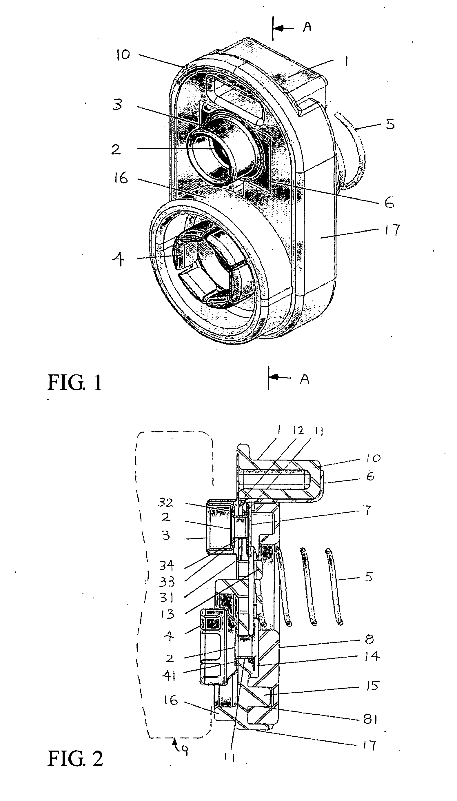
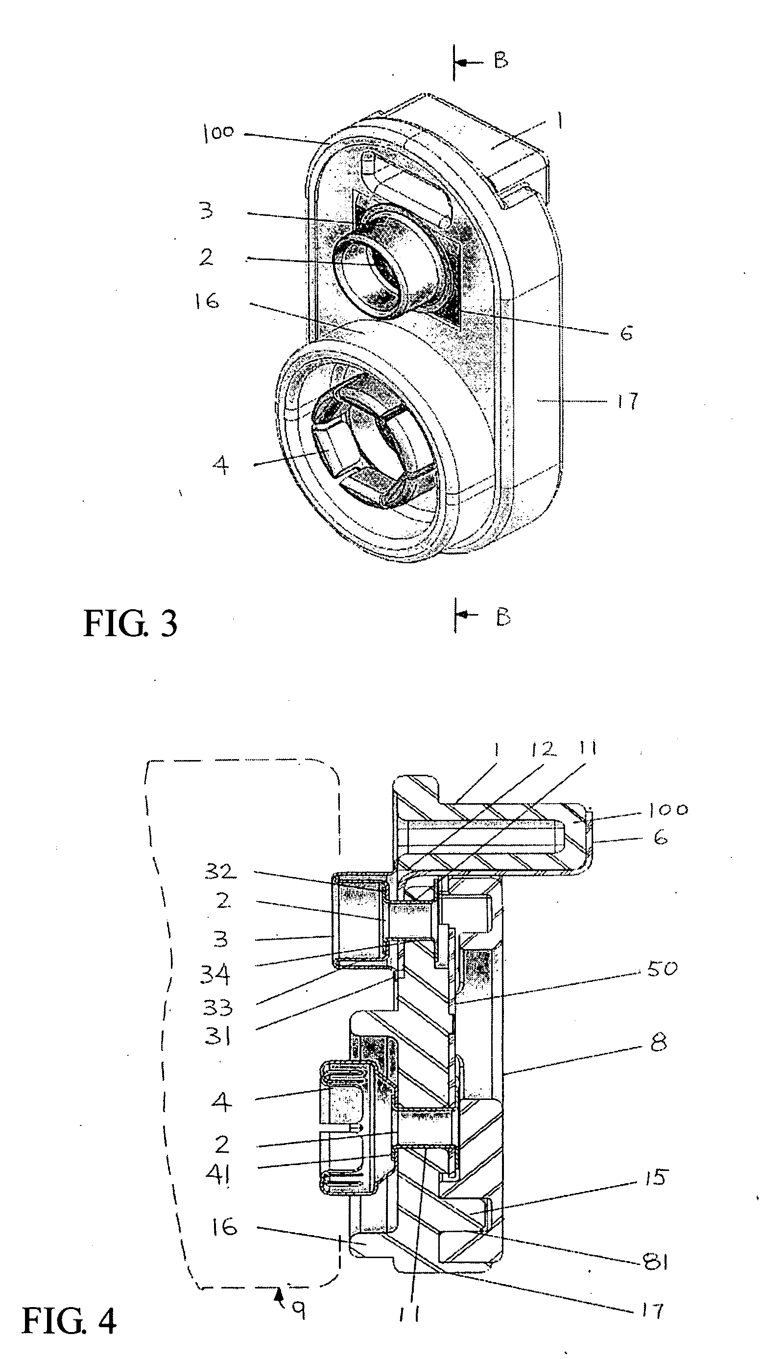
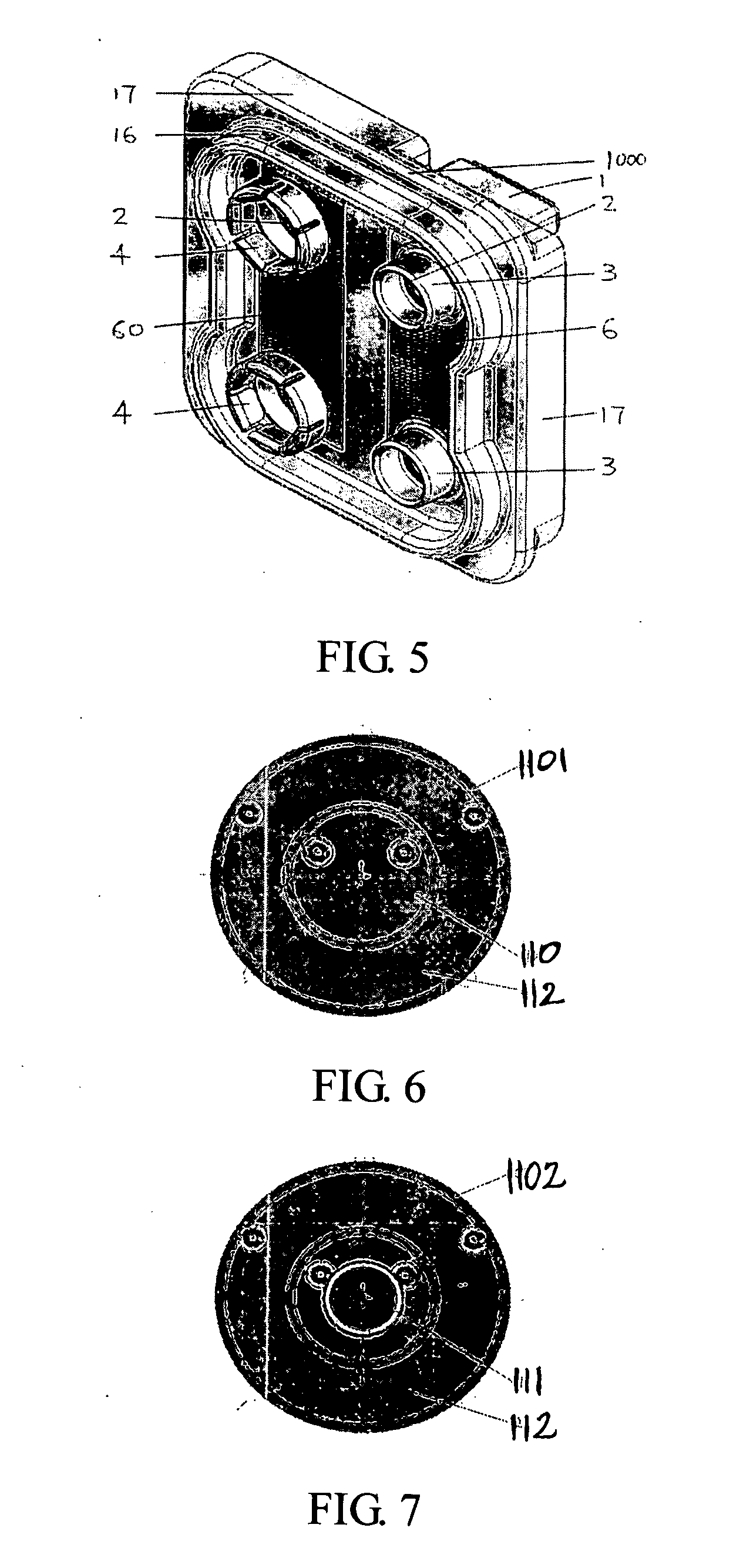
[0023]FIGS. 1-6 show the first, second and third embodiments of the present invention. According to the structure of the invention, the wireless battery snap 10, 100 and 1000 comprises of an insulating support 1, a conductive eyelet 2, a cylindrical plug 3 and a socket electrode 4, a conductive spring 5 or a conductive contact plate 50, a contact plate 6 of the other electrode, an insulating piece 7, an insulating cover 8 and battery 9.

[0024] The insulating support 1 is made of insulating materials by means of injection molding. At least two form electrode holes 11 and a formed strip protruding toward the other side having a slotted base 12 and side wall 17 for securing the conductive contact plate 6, conductive spring 5, or conductive contact plate 50, the eyelet 2 and the insulating cover 8 are provided in the insulating support. The cylindrical plug 3 and the socket electrode 4 are extending through two conductive eyelets 2, to connect to the conductive spring 5 or the contact p...


PUM

PropertyMeasurementUnit
polarityaaaaaaaaaa
distanceaaaaaaaaaa
heightaaaaaaaaaa

Abstract

A wireless battery snap without any leading out electrical wires and which has at least one button with exposed metal for use in an electrical device for connecting the battery which is safer in use. The spring comprises an insulating support, conductive eyelets, cylindrical socket and plug electrode, spring, contact plate, insulating sheet and insulating cover. At least two electrode holes and protruded base, posts and side walls are provided in the insulating support for securing the contact plate, spring, conductive eyelets and insulating cover. The socket and plug electrodes are held by two conductive eyelets on the insulating support and fastened together with the spring and contact plate. Two button electrodes of the battery disposed on the socket and plug electrodes respectively are connected to the contact plate on the insulating support and spring or two contact poles. In use, it is necessary for the invention to have a set of displaceable electrodes of contact detrudes with two independent poles in the electrical device. The spring permanently contacts and depresses on one of the electrodes of the device, when the electrode is displaced, the contact plate connects with the other electrode or disconnects apart therefrom, causing electrical current to flow or stop.

Description

TECHNICAL FIELD [0001] The present invention relates to a wireless battery snap, particularly, one for use in an electrical device for connecting a battery. BACKGROUND OF THE INVENTION [0002] A cylindrical shape rather than a rectangular shape battery is normally used in an electric device as the power supply. One of the reasons being that the electrical wires which protrude from the battery snap make it inconvenient for use. From a technical point of view, the electrical wires which protrude from the battery snap now available in the market may be twisted, stretched and disconnected during use which affect the conductivity of the battery snap. The cylindrical plug and the battery snap socket are exposed and may result in a short circuit causing damage to the electrical device and may result in injury to the user. Generally, a switch for controlling the power supply has to be added to the electrical device. SUMMARY OF THE INVENTION [0003] The Technical Problem to be Solved [0004] To...

Claims


Application Information

Patent Timeline
Patent Type & Authority Applications(United States)
IPC IPC(8): H02J7/00H01M50/216H01M50/244H01M50/269H01M50/503H01M50/51
CPCH01M2/105H01R31/06H01R13/405Y02E60/10H01M50/213
Inventor TSIANG, PUI HONG
Owner TSIANG PUI HONG
Why Eureka
Try Eureka