Color filter panel, display panel having the same and method of manufacturing the same

a color filter and display panel technology, applied in non-linear optics, instruments, optics, etc., can solve the problems of non-uniform distribution, liquid crystal is not uniformly distributed, and the cell gap between the color filter substrate and the tft substrate is not maintained, so as to achieve uniform distribution of liquid crystal. the effect of enhanced uniformity

Active Publication Date: 2006-02-09
SAMSUNG DISPLAY CO LTD
View PDF15 Cites 60 Cited by
  • Summary
  • Abstract
  • Description
  • Claims
  • Application Information

AI Technical Summary

Benefits of technology

[0011] In accordance with the present invention, a color filter panel for enhancing uniformity of distribution of liquid crystal and uniformly maintaining the cell gap between the color filter substrate and the TFT substrate is provided.
[0019] According to the present invention, a height difference between the main column spacer and the sub column spacer is adjusted by the color filter layer, so that the uniformity of distribution of liquid crystal is enhanced and the cell gap between the color filter substrate and the TFT substrate is uniformly maintained.

Problems solved by technology

When forming the liquid crystal layer between the color filter substrate and the TFT substrate, the column spacer may cause non-uniform distribution between the color filter substrate and the TFT substrate.
In detail, when a number of column space is too large, the color filter layer and the TFT substrate are not compressed toward each other, so that the liquid crystal is not uniformly distributed.
On the contrary, when a number of the color filter substrate is too small, a cell gap between the color filter substrate and the TFT substrate is not maintained.
However, forming the main and sub column spacers having the specific height difference between the main column spacer and the sub column spacer is difficult.

Method used


Image

  • Color filter panel, display panel having the same and method of manufacturing the same
  • Color filter panel, display panel having the same and method of manufacturing the same
  • Color filter panel, display panel having the same and method of manufacturing the same

Examples


Embodiment Construction

[0027] It should be understood that the exemplary embodiments of the present invention described below may be modified in many different ways without departing from the inventive principles disclosed herein, and the scope of the present invention is therefore not limited to these particular embodiments. Rather, these embodiments are provided so that this disclosure will be thorough and complete, and will fully convey the concept of the invention to those skilled in the art by way of example and not of limitation.

[0028] Hereinafter, the embodiments of the present invention will be described in detail with reference to the accompanied drawings.

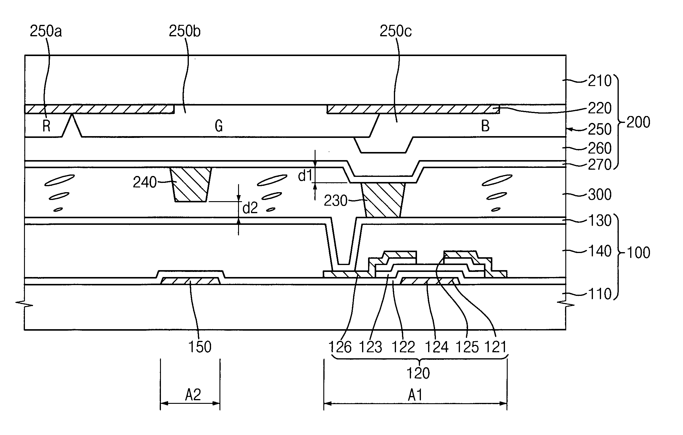
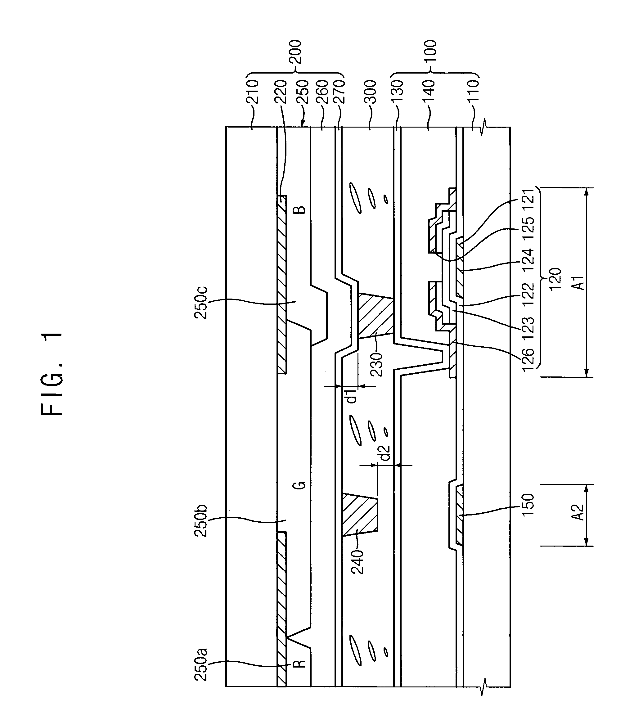
[0029]FIG. 1 is a cross-sectional view illustrating a liquid crystal display panel according to an exemplary embodiment of the present invention. FIG. 2 is a layout illustrating a portion of a TFT substrate in FIG. 1, and FIG. 3 is a layout illustrating a portion of a color filter substrate in FIG. 1.

[0030] Referring to FIGS. 1 through 3, a l...


PUM

PropertyMeasurementUnit
thicknessaaaaaaaaaa
transparentaaaaaaaaaa
thicknessaaaaaaaaaa

Abstract

A color filter substrate includes a transparent substrate, a light-blocking layer, a color filter layer, a first cell gap maintaining member and a second cell gap maintaining member. The transparent substrate has a plurality of pixel regions. Each of the pixel regions includes first and second regions. The light-blocking layer is disposed over the transparent substrate. The light-blocking layer blocks light that leaks through boundaries of the pixel regions. The color filter layer is disposed over the transparent substrate. The color filter layer has a first thickness at the first region and a second thickness that is smaller than the first thickness at the second region. The first cell gap maintaining member is disposed at the first region. The second cell gap maintaining member is disposed at the second region. Therefore, a height difference between the main column spacer and the sub column spacer may be easily adjusted.

Description

CROSS-REFERENCE TO RELATED APPLICATIONS [0001] This application relies for priority upon Korean Patent Application No. 2004-61078 filed on Aug. 3, 2004, the contents of which are incorporated by reference herein in its entirety. BACKGROUND [0002] 1. Field of the Invention [0003] The present invention relates to a color filter panel, a display panel having the color filter panel, and a method of manufacturing the color filter panel. More particularly, the present invention relates to a color filter panel for enhancing the uniformity of distribution of liquid crystal and uniformly maintaining the cell gap between the color filter substrate and the TFT substrate that is to be combined with the color filter substrate uniformly. [0004] 2. Description of the Related Art [0005] A liquid crystal display (LCD) device includes an LCD panel having a TFT substrate, a color filter substrate facing the TFT substrate, and a liquid crystal layer disposed between the TFT substrate and the color filt...

Claims


Application Information

Patent Timeline
Patent Type & Authority Applications(United States)
IPC IPC(8): G02F1/1335
CPCG02F1/13394G02F1/133514G02F1/1339
Inventor LEE, JEONG-HOLEE, KYE-HUNHONG, KWEON-SAMKIM, BAE-HEUK
Owner SAMSUNG DISPLAY CO LTD
Why Eureka
Try Eureka