
Process control system, process control server and process control method

a technology of process control and server, applied in the field of process control system, server and method, can solve the problems of insatiable information, inability to accurately reset the process solely with the information acquired, and inability to ascertain the particular reason for jamming

Inactive Publication Date: 2006-02-09
CANON KK
View PDF19 Cites 28 Cited by
  • Summary
  • Abstract
  • Description
  • Claims
  • Application Information

AI Technical Summary

Benefits of technology

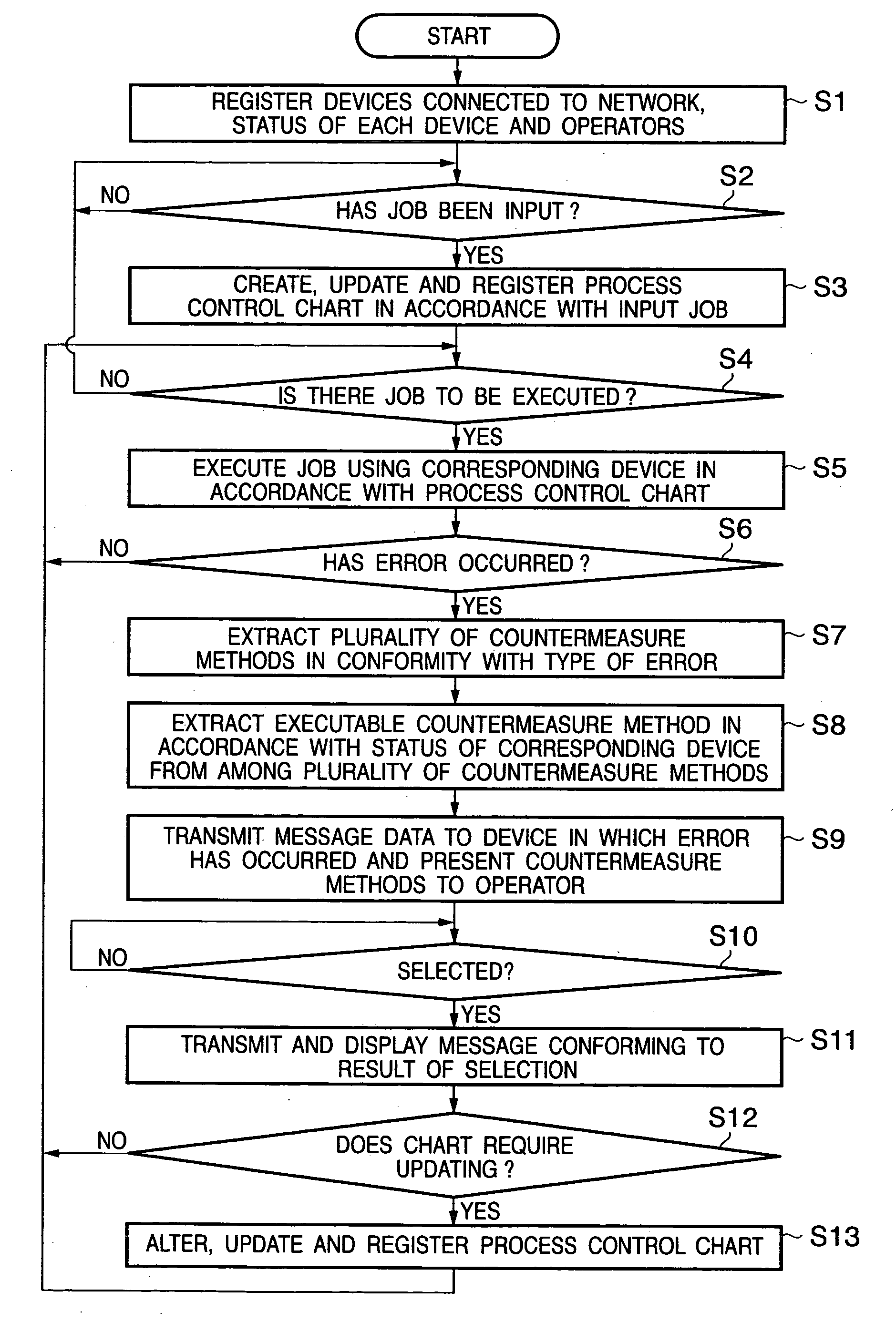
[0012] A feature of the present invention is to provide a process control system, server and method whereby when an error occurs in a device during the execution of a job by the device, it is possible to select an operation in accordance with a type of the error of the device.

Problems solved by technology

This information is not satisfactory as information for resetting the process.
A problem which arises, therefore, is that accurate process reset cannot be performed solely with the information acquired.
Further, in the event that an error of some kind has occurred in the image forming device, display of a specific error message can be presented to the operator using the display unit of the device.
For example, if paper has become jammed in a certain image forming device, the particular reason for jamming cannot be ascertained.
Accordingly, the process control server cannot decide whether this image forming device should be as a device to be assigned a job or whether it should be temporarily excluded from a device to which a job is assigned.
However, present-day process control servers cannot make such flexible decisions and responses as the circumstances demand.
Furthermore, even if the process control server issues an order to perform an operation, the server cannot send this order to the operator upon ascertaining whether the operator is accustomed to this work or what the state of health of the operator is on that particular day.
Such a determination cannot be made and the situation cannot be dealt with using a mechanical control method of a process control server.
However, at a printing site of such scale that a large number of devices are connected in the system, it is difficult for the operator to grasp the overall system and it is highly likely that the decision will be made in accordance with an empirical rule.
Nevertheless, one on-site operator cannot ascertain all the necessary information, such as whether a trimmer has been installed at the printing site, whether the trimmer is in a state where it can be reserved for use, whether a worker skilled at handling the trimmer is available, and whether the work schedule of the trimmer operator will allow him to do the job.

Method used


Image

  • Process control system, process control server and process control method
  • Process control system, process control server and process control method
  • Process control system, process control server and process control method

Examples


second embodiment

[0092]FIG. 11 is a diagram useful in describing the process control chart 907 according to a second embodiment of the present invention. Portions in FIG. 11 identical with those shown in FIG. 5 are designated by like reference characters and need not be described again.

[0093] It is assumed in FIG. 11 that an error of some kind has occurred in the image forming device 401 during execution of “Job-ID: 249”, by way of example. In this case, a message of the kind indicated at 1001 in FIG. 12 is displayed on the display unit 106 of the image forming device 401 with regard to processing of job “Job-ID: 250” that has been scheduled for the image forming device 401 and that follows the job in which the error has occurred. The message displayed is as follows: “AN ERROR HAS OCCURRED IN JOB OF ID: 249. DO YOU WISH TO TRANSFER THE JOB (ID: 250) SCHEDULED NEXT TO ANOTHER IMAGE FORMING DEVICE (402)?”

[0094] This indicates that since an error has occurred in the image forming device 401, the other...

third embodiment

[0098] A third embodiment of the present invention will be described next. In the third embodiment, it is so arranged that a plurality of countermeasure methods for dealing with a specific error that occurs in a certain device are displayed in an order of priority and a desired one of these countermeasure methods can be selected.

[0099]FIG. 14 is a diagram useful in describing an example of display of messages by the process control server 103 according to the third embodiment of the present invention.

[0100] Described here will be a case where jamming has occurred in the image forming device 401 for a fifth time on a single day. Reference numeral 1201 denotes an error message displayed on the display unit 106 of the console 105. The prior art is such that in a case where paper jamming, for example, has occurred, a message instructing that the jammed paper should be removed is merely displayed and sometimes the display is accompanied by an animation. By contrast, the third embodimen...

fourth embodiment

[0111] A fourth embodiment of the present invention will be described next. The fourth embodiment proposes a printing system in which when an operator is allowed to select the contents of an operation as in the third embodiment, resetting of the next process is performed automatically in accordance with an internal order of priority if the operator has not made a selection or decision upon elapse of a prescribed period of time.

[0112]FIG. 15 is a diagram useful in describing an example of display of messages by the process control server 103, as well as occurrence of time-out, according to the fourth embodiment of the present invention. Portions in FIG. 15 identical with those shown in FIG. 14 of the third embodiment are designated by like reference characters and need not be described again.

[0113] Consider a case where the list 1201 ranked in order of priority relating to jamming as described above in the third embodiment is displayed. A time-out occurs if there is no input from t...


PUM


Abstract

Disclosed is a process control system for connecting a plurality of devices and a process control server, which manages the plurality of devices, via a network. The system accepts input of a job, creates a schedule of each device necessitated by the job that has been input and causes the job to be executed by each device based upon the schedule. If an error has occurred in a certain device during execution of the job, the system extracts executable operation contents based upon the schedule from operation contents stored previously with respect to the error, presents the operation contents and allows the operation contents to be selected, and updates the schedule in accordance with operation contents selected by an operator in charge in accordance with the displayed presentation.

Description

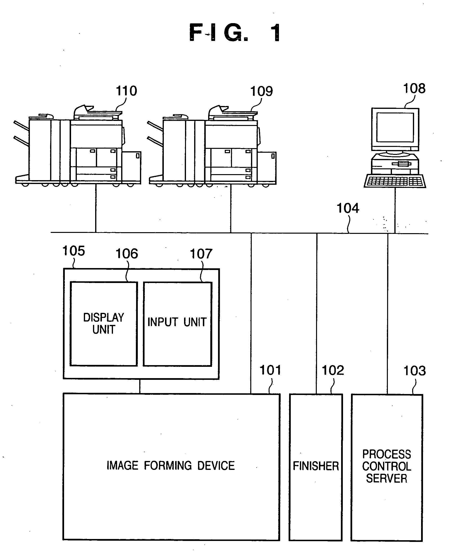
FIELD OF THE INVENTION [0001] This invention relates to a process control system, server and method for controlling an operating process performed among a plurality of devices interconnected via a network. BACKGROUND OF THE INVENTION [0002] At a printing site where printing is performed by POD (Print On Demand), a plurality of each of an image forming device for forming an image on a sheet, an image input device for inputting image data, and a sheet processing device for processing the printed sheets are interconnected via a network. The sheet processing devices are known as a binding device for binding a plurality of sheets, a stapling device for stapling a plurality of sheets and a case making device for covering a bundle of the bound sheets. In the printing site where printing is performed by POD, print processing using a network system, which is based upon a print job generated by a client computer and a print job introduced via the Internet, is executed. At such a printing site...

Claims


Application Information

Patent Timeline
Patent Type & Authority Applications(United States)
IPC IPC(8): G06K15/00
CPCG06F3/1204G06F3/1288G06F3/126G06F3/121
Inventor ABIKO, OSAMU
Owner CANON KK
Learn More