Vehicular headlamp apparatus

Active Publication Date: 2006-02-09
DENSO CORP
View PDF6 Cites 47 Cited by
  • Summary
  • Abstract
  • Description
  • Claims
  • Application Information

AI Technical Summary

Benefits of technology

[0010] The present invention has been made in consideration of the foregoing. It is therefore an object of the present invention to provide a vehicle headlamp apparatus capable

Problems solved by technology

Accordingly, the above-mentioned conventional vehicle headlamp apparatus may not sufficiently ensure the driver's visibility caused by the headlamp's light dist

Method used


Image

  • Vehicular headlamp apparatus
  • Vehicular headlamp apparatus
  • Vehicular headlamp apparatus

Examples


embodiment 1

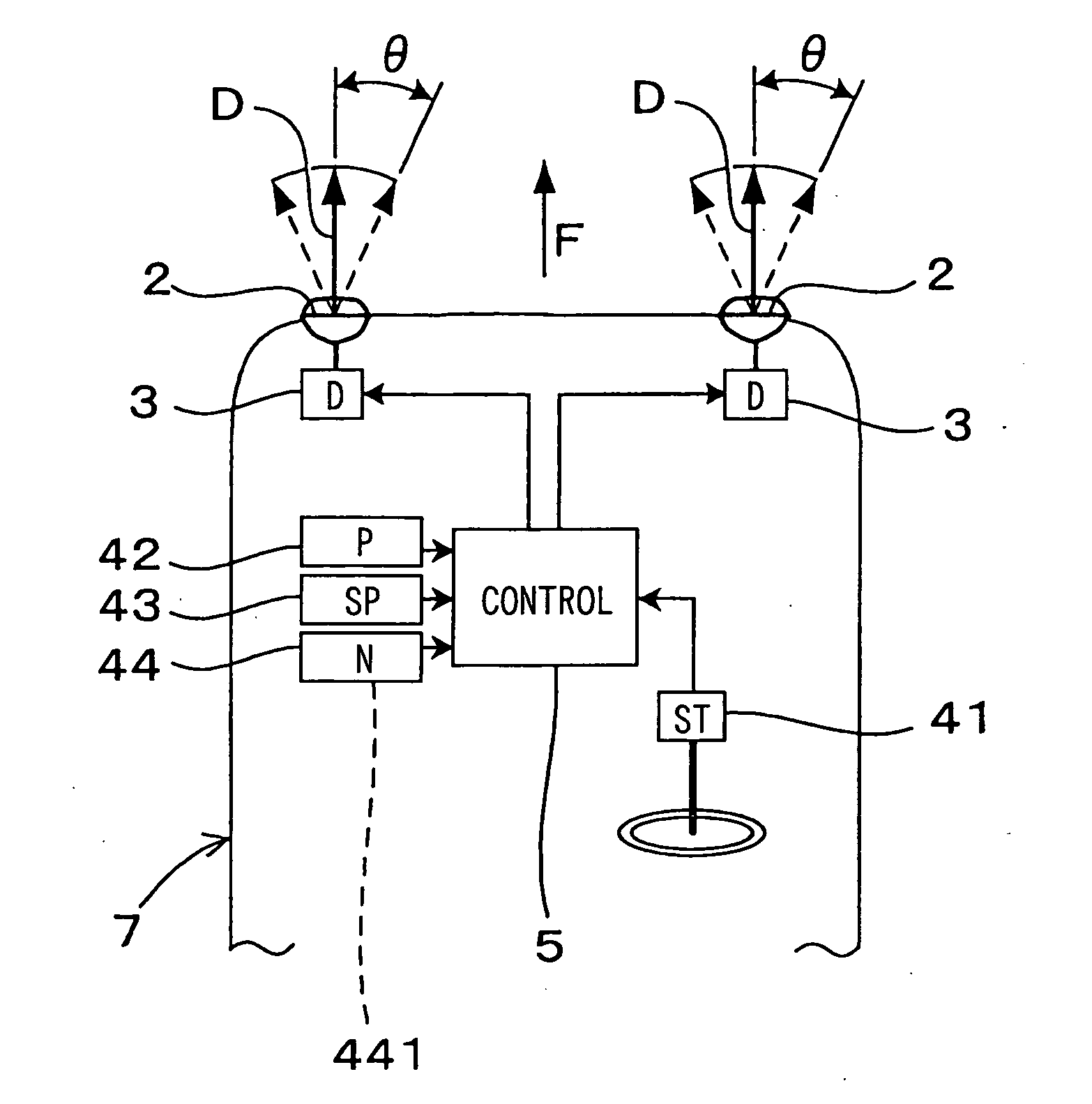
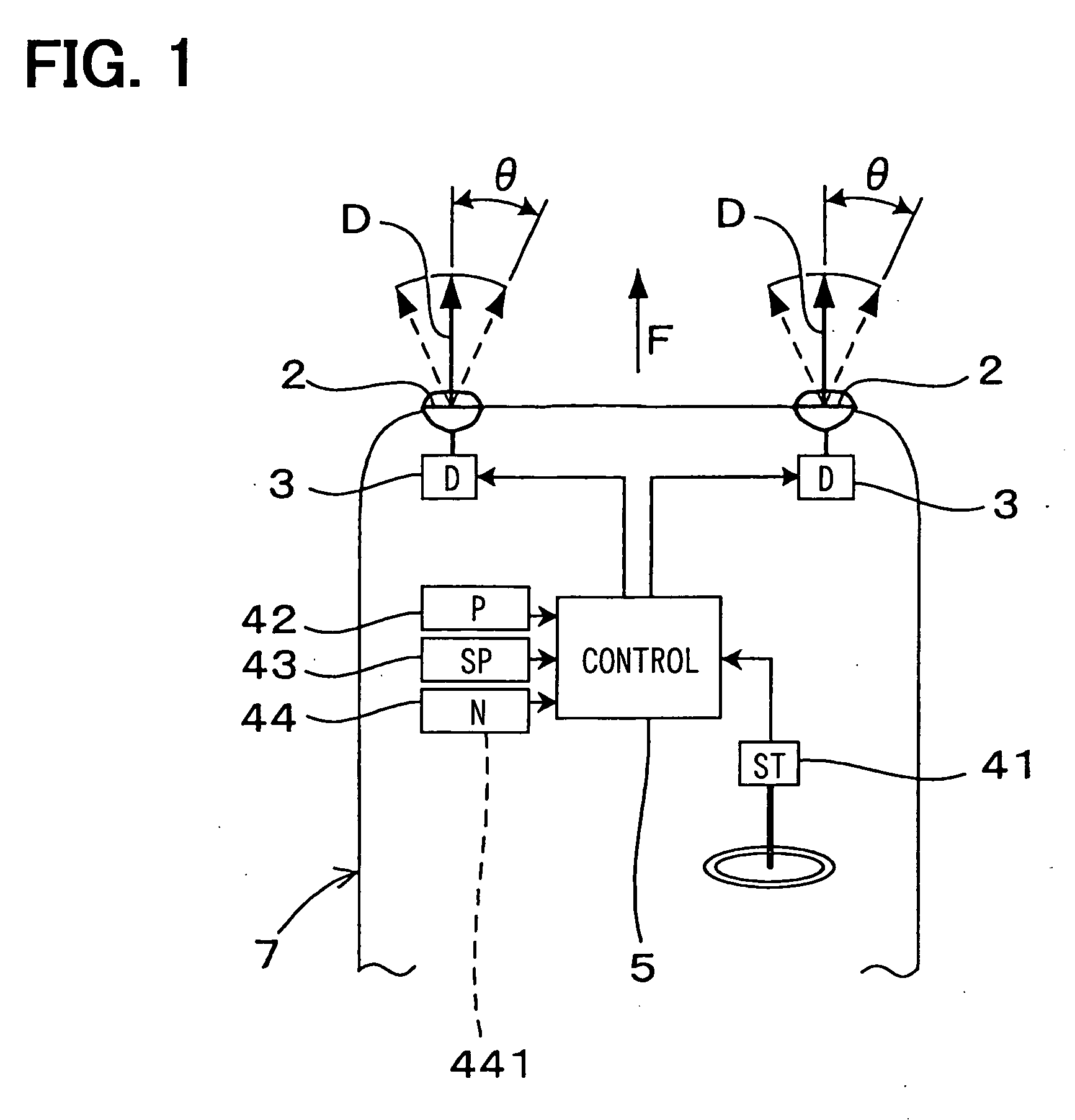
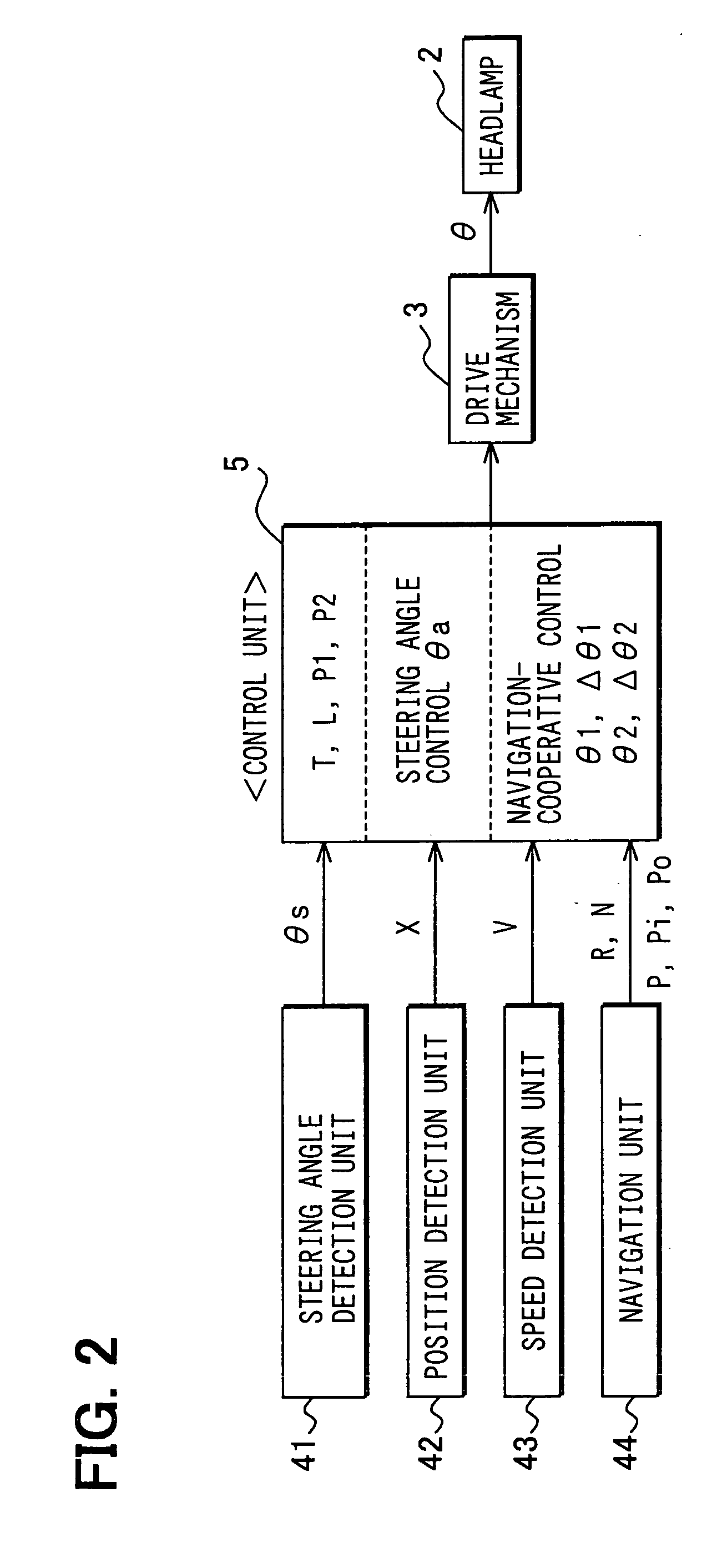
[0285] As shown in FIGS. 1 and 2, a vehicle headlamp apparatus 1 according to the embodiment has: a headlamp 2 as a pair of a right lamp and a left lamp provided at the front of a vehicle 7; a drive mechanism 3 to horizontally move the headlamp 2; a steering angle detection unit 41 to successively detect steering angle θs for the vehicle 7; a position detection unit 42 to successively detect position X of the vehicle 7; a speed detection unit 43 to successively detect speed V of the vehicle 7; a navigation unit 44; and a control unit 5. In this embodiment 1, the headlamp 2 provided at the front of a vehicle 7 means a pair of a right lamp and a left lamp.

[0286] The navigation unit 44 includes a road database 441 that stores a plurality of navigation points P (nodes along a road, as will be applicable to the following description) arranged according to road information.

[0287] The control unit 5 is constructed to selectively provide steering angle control and navigation-cooperative c...

embodiment 2

[0418] As shown in FIGS. 12 through 16, the vehicle headlamp apparatus 1 according to the embodiment only uses the control setup time T to provide the navigation-cooperative control at the entry into the curved road and the navigation-cooperative control at the exit from the curved road.

[0419] Compared to the above-mentioned embodiment 1, the control unit 5 according to embodiment 2 provides the navigation-cooperative control at the entry into the curved road to find the entry control start point P1 using the control setup time T, not using the control setup distance L. While the control setup time T elapses, the control unit 5 gradually varies the swivel angle θ until it reaches the target swivel angle θ1.

[0420] Compared to the above-mentioned embodiment 1, the control unit 5 according to embodiment 2 provides the navigation-cooperative control at the exit from the curved road to find the exit control start point P2 using the control setup time T, not using the control setup dist...

embodiment 3

[0453] This embodiment is constructed so as to independently control swivel angles θ of a pair of left and right headlamps 2.

[0454] As shown in FIG. 17, the control unit 5 according to the embodiment is constructed as follows. When the curved road 82 is a right curved road winding to the right of the traveling direction of the vehicle 7, the control unit 5 provides a right headlamp 2R of the pair of left and right headlamps 2 with the navigation-cooperative control at the entry into the curved road. When the curved road 82 is a left curved road winding to the left of the traveling direction of the vehicle 7, the control unit 5 provides a left headlamp 2L of the pair of left and right headlamps 2 with the navigation-cooperative control at the entry into the curved road. When the curved road 82 is a right curved road, the control unit 5 provides the left headlamp 2L of the pair of left and right headlamps 2 with the navigation-cooperative control at the exit from the curved road. Whe...


PUM


Abstract

A control unit of a vehicular headlamp apparatus can selectively perform steering angle control and navigation-cooperative control. The steering angle control operates a drive mechanism based on a steering angle and a speed of a vehicle to control a headlamp's swivel angle. The navigation-cooperative control operates the drive mechanism using a navigation unit to control the swivel angle. When a current position of the vehicle reaches an entry control start point, the control unit starts navigation-cooperative control at the entry into a curved road. The control unit finds a target swivel angle based on a curvature radius and curved road direction information about the curved road. While the vehicle moves from the entry control start point to a curved road start point, the control unit operates the drive mechanism to gradually change the headlamp's swivel angle to the target swivel angle.

Description

CROSS REFERENCE TO RELATED APPLICATIONS [0001] This application is based on and incorporates herein by reference Japanese Patent Applications No. 2004-231383 filed on Aug. 6, 2004, and No. 2005-140658 filed on May 13, 2005. FIELD OF THE INVENTION [0002] The present invention relates to a vehicle headlamp apparatus constructed to be capable of adjusting a swivel angle in an optical axis direction of a headlamp provided on the front of a vehicle. BACKGROUND OF THE INVENTION [0003] Conventionally, there has been available a vehicle headlamp apparatus for driving at night (e.g., see patent document 1). The apparatus can change a swivel angle in the optical axis direction (light distribution direction) of a headlamp at the vehicle front in response to a steering angle within an area approximately parallel to a road surface. [0004] Generally, a driver drives a vehicle by visually checking a road forward in the traveling direction. When there is a curve in the vehicle's traveling direction...

Claims


Application Information

Patent Timeline
IPC IPC(8): F21V7/00
CPCB60Q1/12B60Q2300/112B60Q2300/122B60Q2300/336B60Q2300/134B60Q2300/322B60Q2300/124
Inventor HORII, YASUTOSHIHASEGAWA, JUNICHISUGIMOTO, TOSHIO
Owner DENSO CORP
Why Eureka
Try Eureka