Autofocus actuator

a technology of autofocus and actuator, which is applied in the direction of mountings, instruments, data recording, etc., can solve the problems of reducing the driving force of the front support flame and the rear support flame in which the lenses are mounted, and achieve the effect of enhancing the driving force of the holder and preventing leakag

Inactive Publication Date: 2006-02-09
MITSUMI ELECTRIC CO LTD
View PDF1 Cites 53 Cited by
  • Summary
  • Abstract
  • Description
  • Claims
  • Application Information

AI Technical Summary

Benefits of technology

[0007] With the above-mentioned problems in mind, it is an object of the present invention to provide an autofocus actuator that can prevent a leakage of the magnetic flux in the yoke, whereby enabling to enhance the driving force of the holder in which lenses are mounted.

Problems solved by technology

Therefore, magnetic fields in the outer gap and the inner gap between the magnets and the yoke become smaller, which leads to a problem in that the driving force of the front support flame and the rear support flame in which the lenses are mounted is decreased.

Method used


Image

  • Autofocus actuator
  • Autofocus actuator
  • Autofocus actuator

Examples


Embodiment Construction

[0037] An autofocus actuator proposed by the present inventor and used as the premise of the present invention will be first described in detail with reference to the drawings attached.

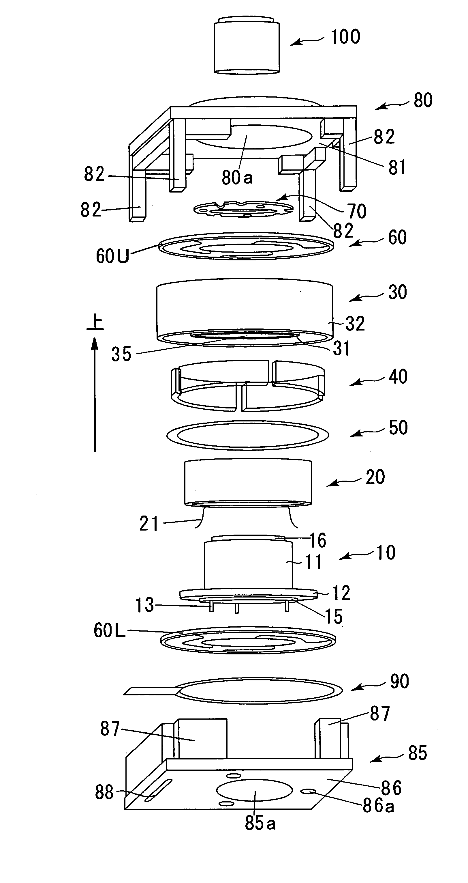
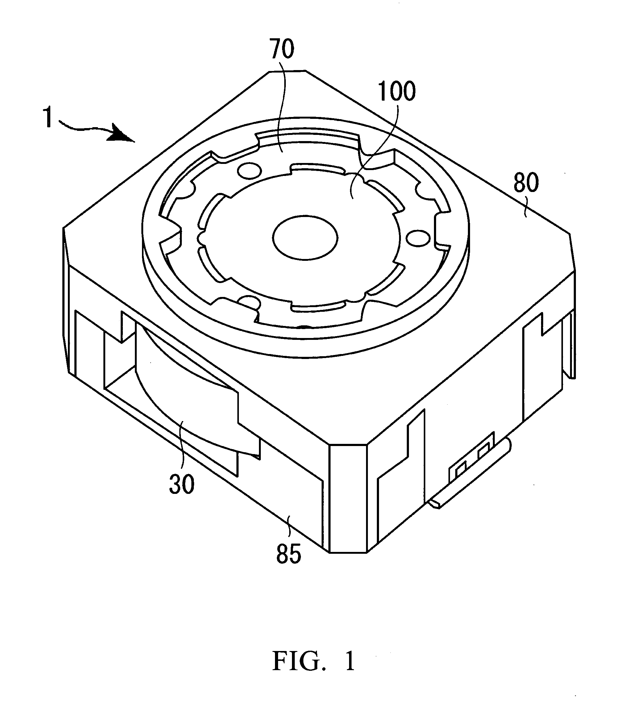
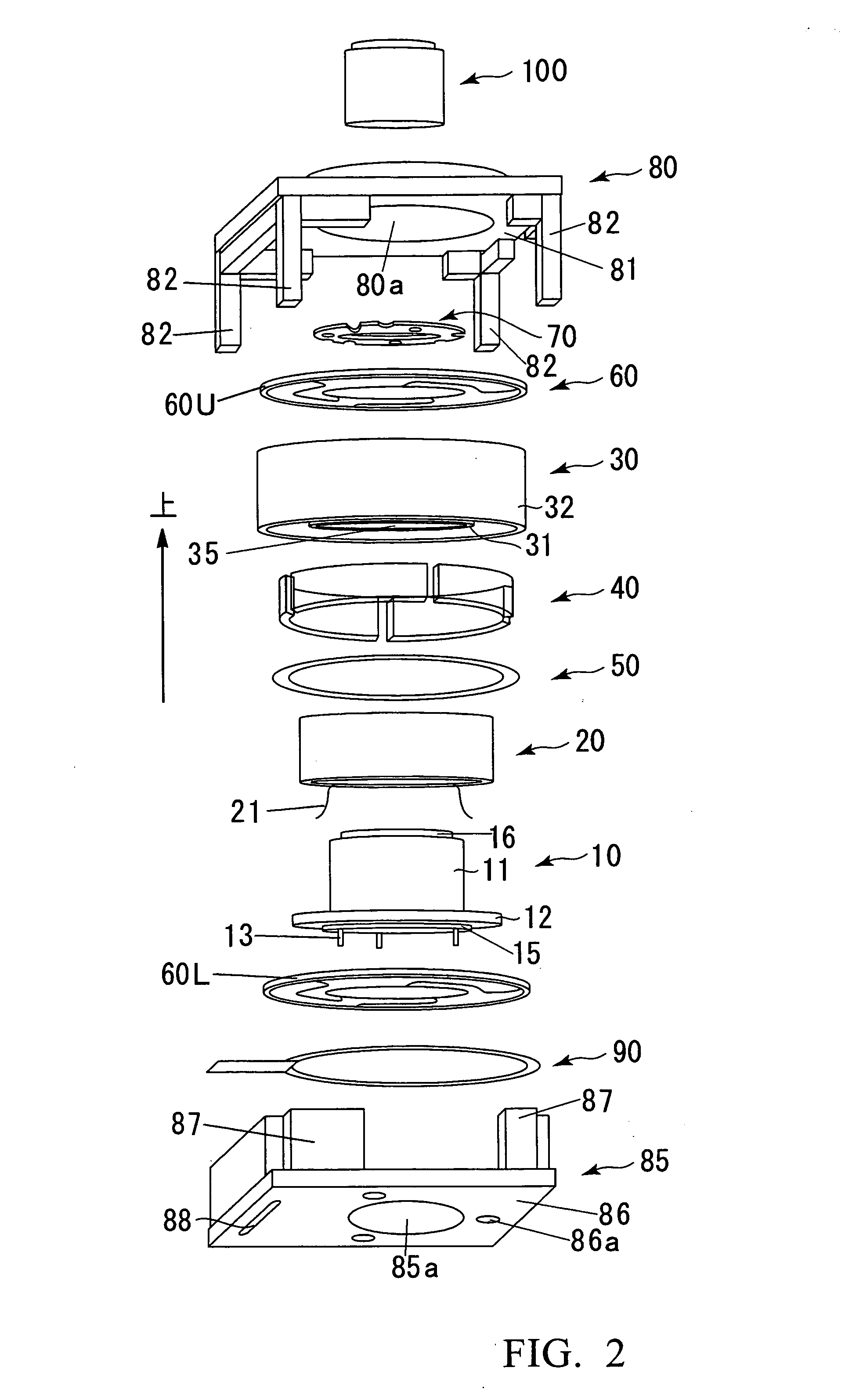
[0038] Referring to FIG. 1, there is shown perspective view showing the external appearance of the autofocus actuator. FIG. 2 is an exploded perspective view of the autofocus actuator shown in FIG. 1. FIG. 3 is a schematic cross-sectional view of the autofocus actuator shown in FIG. 1.

[0039] As shown inFIGS. 1, 2 and 3, the autofocus actuator 1, simply referred to as “actuator” hereinbelow, is generally composed of: a holder 10 including a hollow body portion 11 having one end to which a lens assembly 100 is attached, and a flange portion 12 provided along the perimeter of the other end of the hollow body portion 11; a coil 20 fixedly secured to the holder 10 in a spaced-apart relationship with the outer circumference of the hollow body portion 11; a cylindrical yoke 30 including an inner cylindrica...


PUM

PropertyMeasurementUnit
magnetic fieldaaaaaaaaaa
magnetic fluxaaaaaaaaaa
thicknessaaaaaaaaaa

Abstract

An aoutofocus actuator is provided with a yoke 30 that is constructed so as to receive a coil 20. The yoke 30 includes a plurality of permanent magnets 40 that are positioned so as to face the coil 20 with a space left therebetween. A ring-shaped magnetic member 50 is disposed on the lower surfaces of these permanent magnets 40, whereby preventing the magnetic flux from being leaked out downwards from the permanent magnets 40 at the open side of the yoke 30 which is opposite to the connecting portion 34. According to this, it becomes possible to enhance a driving force of the actuator.

Description

BACKGROUND OF THE INVENTION [0001] 1. Field of the Invention [0002] The present invention relates to an autofocus actuator, and more specifically to an autofocus actuator that can be employed in digital cameras or other small-sized electronic apparatuses equipped with a camera, e.g., cellular phones. [0003] 2. Description of the Related Art [0004] In digital cameras, an actuator that can displace a lens in an optical axis direction is employed for the sake of autofocusing and zooming operations. This type of actuator is adapted to displace the lens in the optical axis direction by virtue of an interaction between the magnetic field generated by the electricity flowing through a coil and the magnetic field of a permanent magnet. In recent years, a need exists for the function of autofocus even in a camera mounted to cellular phones, because the number of pixels of a picture-taking element for use in the cellular phone camera tends to increase up to the order of mega pixels greater th...

Claims


Application Information

Patent Timeline
Patent Type & Authority Applications(United States)
IPC IPC(8): G11B7/00
CPCG02B7/102
Inventor OSAKA, TOMOHIKO
Owner MITSUMI ELECTRIC CO LTD
Why Eureka
Try Eureka