
Method and apparatus for receiving signals in MIMO system

Inactive Publication Date: 2006-02-09
SAMSUNG ELECTRONICS CO LTD
View PDF3 Cites 37 Cited by
  • Summary
  • Abstract
  • Description
  • Claims
  • Application Information

AI Technical Summary

Benefits of technology

[0011] An object of the present invention is to substantially solve at least the above problems and / or disadvantages and to provide at least the advantages below. Accordingly, an object of the present invention is to provide a MIMO receiver having relatively low complexity that improves system performance.
[0012] Another object of the present invention is to apply to a MIMO receiver an SIC mechanism that can minimize the number of inverse matrix calculations for detecting signals received via multiple antennas.
[0013] A further object of the present invention is to provide a MIMO receiver that enables effective interference cancellation through reliability normalization.

Problems solved by technology

However, it is very difficult to physically construct a system that incorporates the D-BLAST scheme.
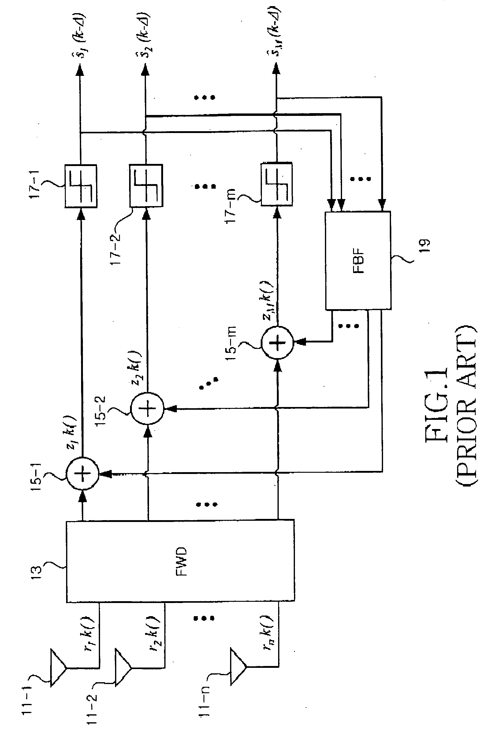
However, in the MIMO MMSE-DFE receiver, data streams having different error rates are fedback, causing deterioration in the system performance.
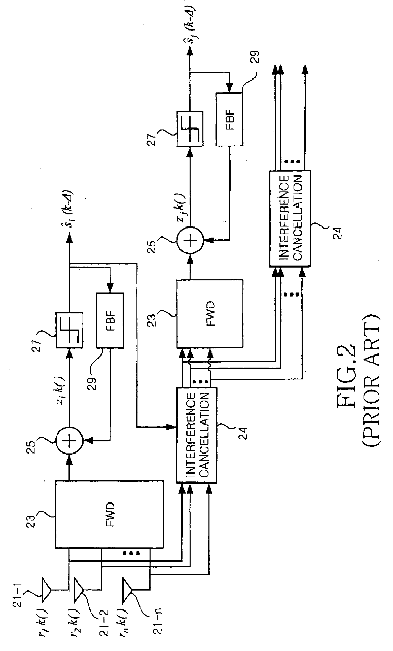
However, the OSIC-DFE receiver is very complex, since inverse matrix calculations with respect to an input self-correlation matrix corresponding to the square of the number of transmitting antennas are required.
Also, in the OSIC-DFE receiver, an increase in the BER (Bit Error Rate) of an initially detected data stream causes error propagation to the data streams detected by subsequent detecting units, deteriorating system performance.

Method used


Image

  • Method and apparatus for receiving signals in MIMO system
  • Method and apparatus for receiving signals in MIMO system
  • Method and apparatus for receiving signals in MIMO system

Examples


Embodiment Construction

[0038] A preferred embodiment of the present invention will be described herein below with reference to the accompanying drawings. In the following description, well-known functions or constructions are not described in detail since they would obscure the invention in unnecessary detail.

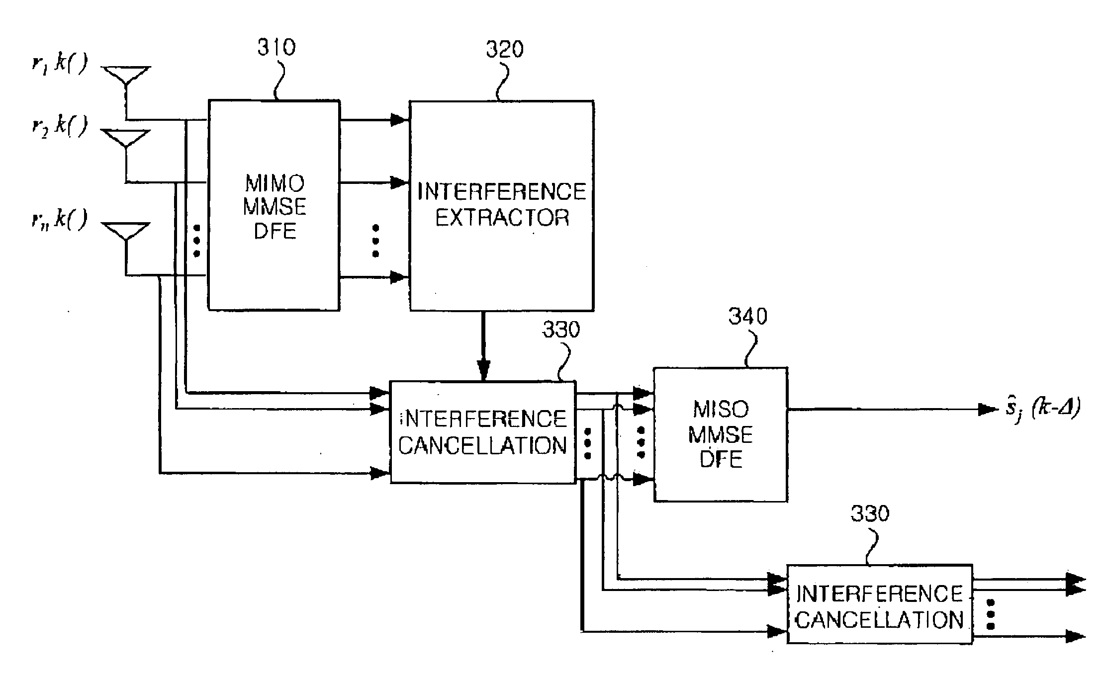
[0039]FIG. 3 is a block diagram of a MIMO receiving apparatus according to a preferred embodiment of the present invention.

[0040] As shown in FIG. 3, the MIMO receiving apparatus includes a MIMO MMSE-DFE 310, which detects the data streams transmitted from the m transmitting antennas by receiving signals via the n receiving antennas and determines the processing priorities of the detected data streams, an interference extractor 320, which calculates the reliability coefficients of the data streams by detecting the SINRs of the detected data streams and outputs the signals obtained by multiplying the calculated reliability coefficients by the corresponding data streams, MISO MMSE-DFEs 340, the numbe...


PUM


Abstract

An improved receiver for a multicarrier-based MIMO (Multiple-Input Multiple-Output) system is provided. A MIMO receiving apparatus includes a detection priority decision unit, which receives via N receiving antennas signals transmitted from M transmitting antennas and determines the detection priorities of the signals, and a signal detector, which successively detects the signals in a decreasing order from a signal having a higher priority according to the detection priorities determined by the detection priority decision unit. System complexity can be reduced by minimizing the number of the inverse matrix calculations required for an SIC mechanism using one MIMO DFE and MISO DFEs corresponding to the number of transmitting antennas.

Description

PRIORITY [0001] This application claims priority under 35 U.S.C. § 119 to an application entitled “MIMO Receiver in MIMO System” filed in the Korean Intellectual Property Office on Aug. 4, 2004 and assigned Serial No. 2004-61491, the contents of which are incorporated herein by reference. BACKGROUND OF THE INVENTION [0002] 1. Field of the Invention [0003] The present invention relates generally to a wireless communication system, and in particular, to an improved receiver for a multicarrier-based MIMO (Multiple-Input Multiple-Output) system. [0004] 2. Description of the Related Art [0005] A MIMO system equips multiple antennas for both a transmitter and a receiver in order to raise spectrum efficiency. The MIMO system is undergoing great advances. For communication systems based on MIMO technology, a D-BLAST (Diagonal Bell Labs Layered Space-Time) scheme of diagonally transmitting a data stream via multiple transmitting antennas has been suggested. When the D-BLAST scheme is used, a...

Claims


Application Information

Patent Timeline
IPC IPC(8): H04L1/02
CPCH04L25/03057H04L2025/0349H04L2025/03375H04B7/0413H04B7/0854
Inventor KIM, HYOUN-KUKPARK, HYUN-CHEOLSUH, SEUNG-BUMCHOI, EOI-YOUNG
Owner SAMSUNG ELECTRONICS CO LTD
Learn More