Energy density control system using a two-dimensional energy density sensor

a control system and energy density technology, applied in noise generation, ear treatment, instruments, etc., can solve the problems of olson and may electronic sound absorber instability at higher frequencies, interference with operator vision, flexibility, comfort, etc., to reduce noise in an enclosure and minimize energy density

Active Publication Date: 2006-02-09
BRIGHAM YOUNG UNIV
View PDF14 Cites 14 Cited by
  • Summary
  • Abstract
  • Description
  • Claims
  • Application Information

AI Technical Summary

Benefits of technology

[0009] In accordance with a disclosed embodiment, a method of reducing noise in an enclosure is described. The method includes receiving at least one reference signal; receiving pressure signals from no more than two substantially orthogonally placed pairs of acoustic sensors, where one pair of acoustic sensors is in the x-direction and one pair of acoustic sensors is in the y-direction, and where the acoustic sensors are placed in a plane which is substantially parallel and in proximity to an inner surface of the enclosure; using the pressure signals and the reference signal to generate an output signal to minimize energy density at a location of the acoustic sensors; and sending the output signal to an acoustic actuator.

Problems solved by technology

Unfortunately, passive noise control systems can be bulky and work best on middle and high frequency sounds.
Unfortunately, the Olson and May electronic sound absorber was unstable at higher frequencies.
Unfortunately, acoustic sensors located in this manner often interfere with the operator's vision, flexibility, and comfort.
In addition, such acoustic sensor placement tends to provide only localized control, rather than global control of unwanted noise.
A drawback of existing ED ANC systems is the additional computing power required to perform the calculations with the three-dimensional inputs forming the error signal.

Method used


Image

  • Energy density control system using a two-dimensional energy density sensor
  • Energy density control system using a two-dimensional energy density sensor
  • Energy density control system using a two-dimensional energy density sensor

Examples


Embodiment Construction

[0019] Reference will now be made in detail to the present exemplary embodiments, examples of which are illustrated in the accompanying drawings. Wherever possible, the same reference numbers will be used throughout the drawings to refer to the same or like parts.

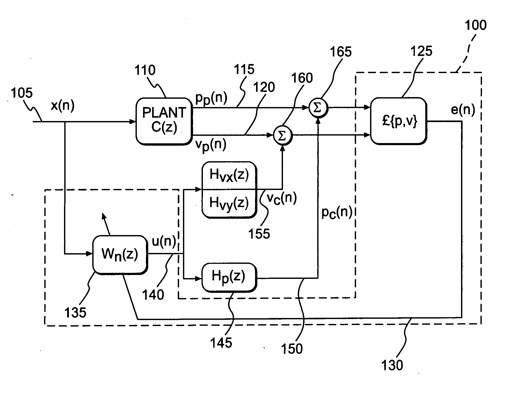
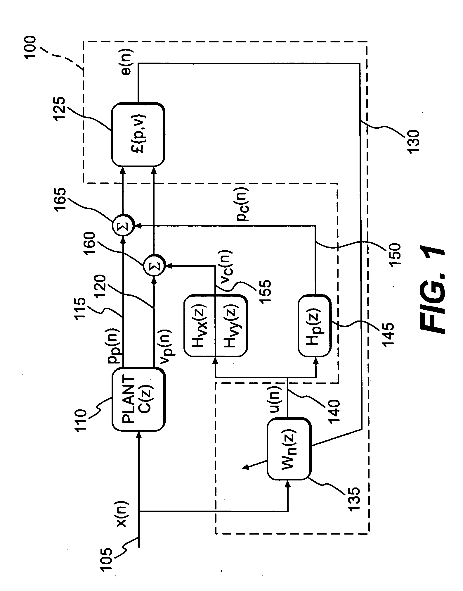
[0020] Unlike energy density active noise cancellation systems that use a three-dimensional sensor to sense the energy density and provide the raw inputs for an error signal to a control system, the present system utilizes a two-dimensional sensor to provide an error signal to the control system. By mounting the two-dimensional sensor on or relatively close to a rigid surface within an enclosed space, such as a vehicle cabin, and orienting the acoustic sensors in a plane that is parallel to the rigid surface, the velocity component of the particle velocity in the direction normal to the rigid surface is known, i.e., zero. Thus, the inventors have discovered that a two-dimensional sensor may be used in place of a three-dime...


PUM


Abstract

A system and method of reducing noise in an enclosure is disclosed. The method includes receiving at least one reference signal; receiving pressure signals from no more than two substantially orthogonally placed pairs of acoustic sensors, where one pair of acoustic sensors is in the x-direction and one pair of acoustic sensors is in the y-direction, and where the acoustic sensors are placed in a plane which is substantially parallel and in proximity to an inner surface of the enclosure; using the pressure signals and the reference signal to generate an output signal to minimize energy density at a location of the acoustic sensors; and sending the output signal to an acoustic actuator.

Description

TECHNICAL FIELD [0001] The method and system disclosed relate to the field of acoustic noise reduction, and more specifically, a system for and method of using one or more two-dimensional energy density sensors feeding a control system to effectively diminish acoustic noise. BACKGROUND [0002] Over the years, many attempts have been made to eliminate unwanted or harmful sounds, i.e., noise. The most used technique is passive noise cancellation, which attempts to eliminate noise by muffling the noise with dampers. Passive noise control is often performed with insulation, ceiling tiles, and mufflers. Unfortunately, passive noise control systems can be bulky and work best on middle and high frequency sounds. [0003] An attractive alternative to passive noise cancellation is active noise cancellation (“ANC”). Active noise cancellation is sound field modification by electro-acoustical means, generally by generating acoustical signals that are out of phase with the noise. In essence, active...

Claims


Application Information

Patent Timeline
Patent Type & Authority Applications(United States)
IPC IPC(8): A61F11/06G10K11/16H03B29/00G10K11/178
CPCG10K11/1786G10K11/17817G10K11/17854G10K11/17857G10K11/17883G10K11/17885G10K11/178
Inventor SOMMERFELDT, SCOTT DAVIDFABER, BENJAMIN MAHONRI
Owner BRIGHAM YOUNG UNIV
Why Eureka
Try Eureka