Hydrodynamic bearing device

a bearing device and hydrodynamic technology, applied in the direction of bearings, shafts and bearings, rotary bearings, etc., can solve the problems of increasing the number of parts, increasing the cost, and increasing the number of steps of the method, so as to prevent the stiffness of the radial bearing from decreasing, and stable non-contact rotation

Inactive Publication Date: 2006-02-09
NIPPON DENSAN CORP
View PDF15 Cites 19 Cited by
  • Summary
  • Abstract
  • Description
  • Claims
  • Application Information

AI Technical Summary

Benefits of technology

[0013] An object of the present invention is to provide a hydrodynamic bearing device including a sleeve made of sintered metal that can prevent working fluid, such as oil, from leaking externally. A further object of the present invention is to prevent stiffness of the radial bearing from decreasing. Still yet another object of the present invention is to maintain an appropriate bearing gap of a thrust bearing or a radial bearing to ensure stable non-contact rotation.

Problems solved by technology

Since the sleeve 101 and the sleeve cover 111 are individual parts, the number of parts increases and the cost is also increased.
Consequently, the method has many steps and a high cost.

Method used


Image

  • Hydrodynamic bearing device
  • Hydrodynamic bearing device
  • Hydrodynamic bearing device

Examples


first embodiment

[0039] Hereinafter, the hydrodynamic bearing device according to a first embodiment of the present invention will be described with reference to FIGS. 1-4. The hydrodynamic bearing device of the present invention is especially useful as a spindle motor having a low cost and high reliability.

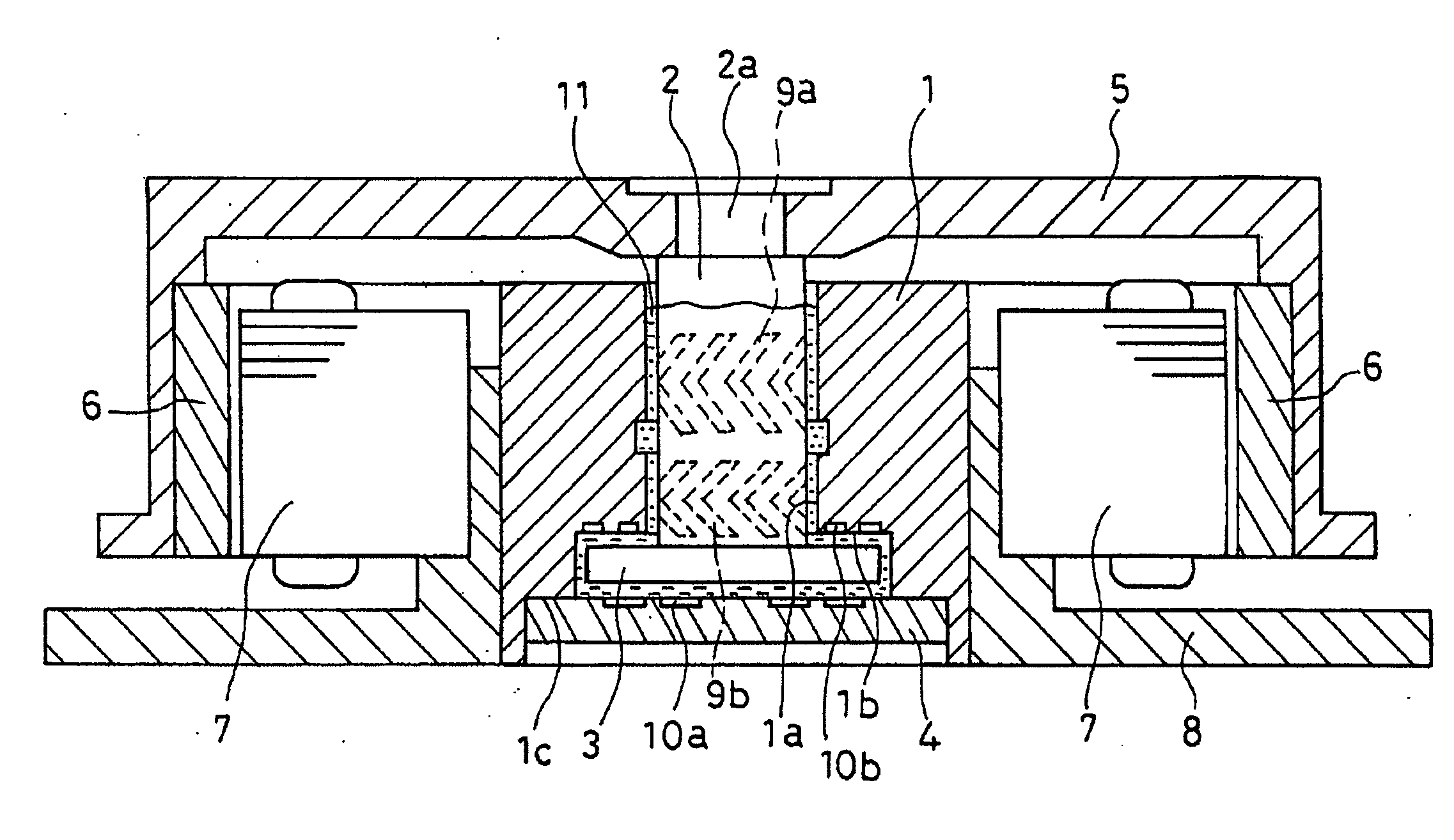
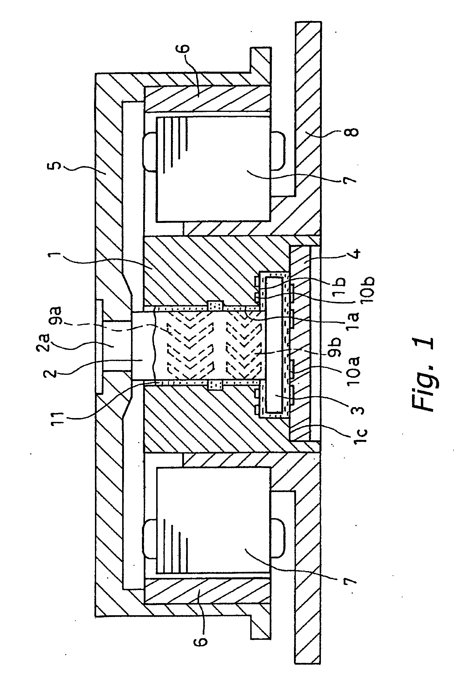
[0040]FIG. 1 is a cross sectional view of a spindle motor including a hydrodynamic bearing device according to a first embodiment of the present invention. As shown in FIG. 1, a sleeve 1 having a bearing bore 1a is made of a sintered body or sintered metal produced by sintering powdered metal containing at least one of iron, an iron alloy, copper and a copper alloy. The sleeve 1 is fixed to a base 8. A shaft 2 is made of a metal that is not a sintered body, and is inserted in the bearing bore 1a in a rotatable manner. The shaft 2 has a thrust flange 3 that is formed integrally therewith. The sleeve 1 includes a stepped end portion 1b that is coaxial with the bearing bore 1a. The stepped end port...

second embodiment

[0058] A hydrodynamic bearing device according to a second embodiment of the present invention will be described with reference to FIGS. 5, 6 and 7. FIG. 5 is a cross sectional view of the hydrodynamic bearing according to a second embodiment. As shown in FIG. 5, a sleeve 40 having a bearing bore 40a is a cylindrical sintered body. The inner surface of the bearing bore 40a is provided with radial dynamic pressure generating grooves 9a and 9b that are formed by a cold plastic process method (component rolling method) or the like. The lower end face of the sleeve 40 in FIG. 5 is provided with thrust dynamic pressure generating grooves 10b. The sleeve 40 has independent pores in the same way as the sleeve 1 in the first embodiment.

[0059] The thrust member 44 of the thrust bearing portion is a saucer-like member made of a sintered metal or a metal material that is not a sintered metal. The thrust member 44 has a circular recess 44a. A diameter and a depth of the recess 44a are adapted ...


PUM

PropertyMeasurementUnit
grain diameteraaaaaaaaaa
diameteraaaaaaaaaa
depthaaaaaaaaaa

Abstract

A hydrodynamic bearing device is provided for use with a spindle motor. The hydrodynamic bearing device has a sleeve made of a sintered metal that is obtained by sintering a sintering material that is iron, an iron alloy, copper, a copper alloy or a mixture thereof. This sintered metal has independent pores, which do not communicate with each other, by selecting conditions for forming a desired sintered body within a predetermined range. The conditions includes a grain size of powdered metal of a material for the sintered metal, a molding pressure when the molded body is formed, sintering temperature and sintering period in the sintering step.

Description

CROSS-REFERENCE TO RELATED APPLICATIONS [0001] This application claims priority under 35 U.S.C. § 119 to Japanese Patent Application No. 2004-229825. The entire disclosure of Japanese Patent Application No. 2004-229825 is hereby incorporated herein by reference. BACKGROUND OF THE INVENTION [0002] 1. Field of the Invention [0003] The present invention generally relates to a hydrodynamic bearing device utilizing a dynamic pressure and a method for manufacturing the device. [0004] 2. Background Information [0005] In recent years, a storage capacity of a recording apparatus or the like using a disk or the like has been increasing, and a data transmission rate thereof has been increasing as well. A high speed and a high precision of rotation is necessary for a spindle motor that is used for such a recording apparatus. Therefore, a hydrodynamic bearing device is used for a rotation shaft portion of the spindle motor. A conventional hydrodynamic bearing device will be described below with ...

Claims


Application Information

Patent Timeline
Patent Type & Authority Applications(United States)
IPC IPC(8): F16C32/06
CPCF16C17/107F16C33/107F16C33/103F16C2370/12
Inventor HAMADA, TSUTOMUASADA, TAKAFUMIOHNO, HIDEAKI
Owner NIPPON DENSAN CORP
Why Eureka
Try Eureka