
Rolling bearing of ceramic and steel engaging parts

Active Publication Date: 2006-02-09
SCHAEFFLER TECH AG & CO KG
View PDF23 Cites 30 Cited by
  • Summary
  • Abstract
  • Description
  • Claims
  • Application Information

AI Technical Summary

Benefits of technology

[0012] Therefore, the object of the invention is to provide

Problems solved by technology

In general, therefore, rolling pairings in which both components are made from ceramic, and in particular rolling pairings in which one rolling part is made from steel and the other is made from ceramic, are not able to withstand as high a load as rolling pairings in which both contact parts are made from steel.
However, as has emerged and as has also been described in the prior art cited above, under certain circumstances ceramic components which have suffered preliminary damage as a result of impurities and inclusions and pores, cracking nuclei and microcracks and overloading and / or as a result of foreign particles in the rolling contact, have initially proven to still have a long service life.
Locally high contact pressures caused by particles which have broken off from the ceramic components and entered the rolling contact may damage the outer layer of the raceways in such a way that microcracks are formed.
These microcracks then propagate to produce pitting and further, extensive damage.
These break-out locations cause the steel surface to be highly stressed as a result of abrasive wear.
As a result, at high rotational speeds and loads, the rate at which damage progresses may be drastically increased.
However, the rolling contact is endangered, in particular in bearings which are greatly influenced by the surroundings, by foreign particles which pass into the rolling contact, for example together with the lubricant.

Method used


Image

  • Rolling bearing of ceramic and steel engaging parts
  • Rolling bearing of ceramic and steel engaging parts
  • Rolling bearing of ceramic and steel engaging parts

Examples


Embodiment Construction

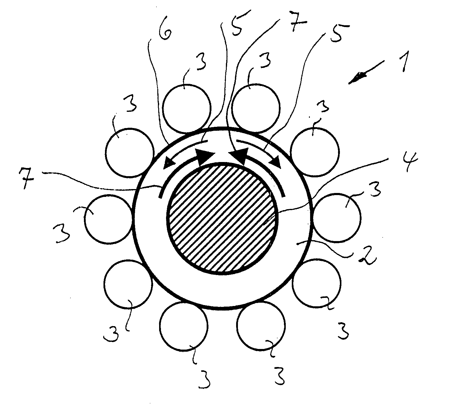
[0096]FIG. 1 shows, as an exemplary embodiment of the invention, a roller bearing 1 comprising an inner ring 2 and rolling bodies 3 in the form of balls. The balls are made from ceramic. The balls and the inner ring 2 form the rolling parts. The inner ring 2 is seated with a press fit on a shaft 4. The shaft 4 rotates at high rotational speeds in the clockwise or counterclockwise direction as desired. The forces from the press fit and the centrifugal forces from the rotation generate tensile stresses 5 (circumferential stresses) in the outer layer 6 of the inner ring 2. At the unfitted ring, the microstructure of the outer layer 6 has residual compressive stresses 7 which are superimposed in opposing fashion on the tensile stresses 5 and compensate for the latter on account of their greater magnitude and their opposite direction of action to the tensile stresses.

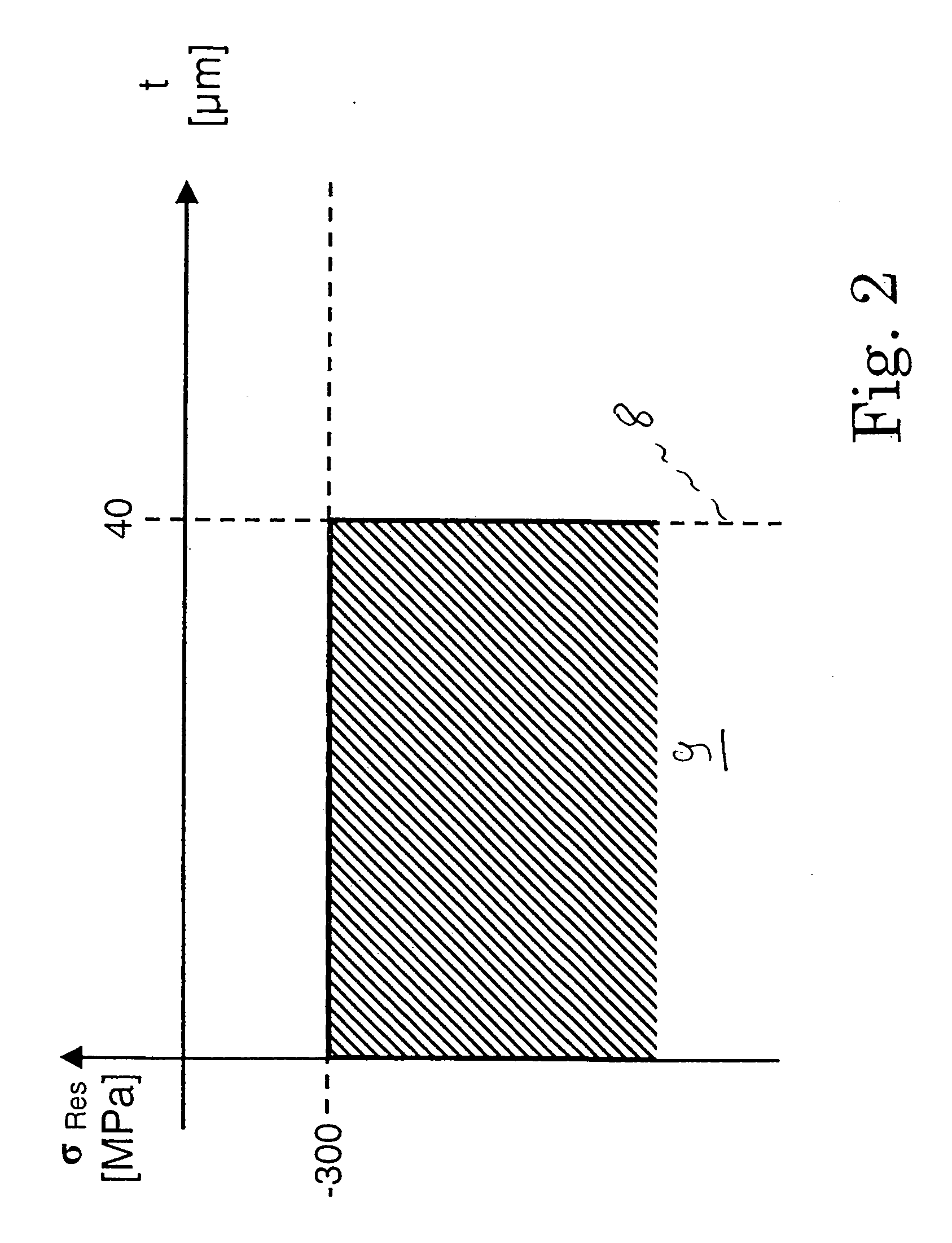
[0097]FIG. 2 shows the results of the invention in diagram form. The residual compressive stresses ores in MPa for a load...


PUM

PropertyMeasurementUnit
Temperatureaaaaaaaaaa
Timeaaaaaaaaaa
Percent by massaaaaaaaaaa

Abstract

A roller bearing having two cooperating rolling parts of which one is of ceramic and the other of a steel. The steel part is of such structure and / or material and / or is so produced to cause residual compressive stresses to form beneath the contact surface of the steel part, at least in a load-free state, down to a depth.

Description

CROSS REFERENCE TO RELATED APPLICATION [0001] This application is based upon and claims benefit of U.S. Provisional Application 60 / 598,784, filed on Aug. 4, 2004, to which a claim of priority is hereby made.FIELD OF THE INVENTION [0002] The invention relates to a rolling bearing, having at least one first rolling part made from a ceramic material and having at least one second rolling part made from a steel. BACKGROUND OF THE INVENTION [0003] Accordingly, the invention relates to hybrid bearings. Hybrid bearings are rolling bearings which have bearing rings, or at least the raceways of the bearing rings, made from steel and which are provided with rolling bodies made from ceramic, or in which at least one bearing ring is made from ceramic and the rolling bodies are made from steel. [0004] The materials used for the ceramic rolling bearing element are all industrial ceramics, in particular silicon nitride (Si3N4), but also silicon carbides and also aluminum and zinc oxides. The use, ...

Claims


Application Information

Patent Timeline
IPC IPC(8): F16C33/58F16C33/32F16C33/62
CPCF16C33/32F16C33/62Y10T29/49689Y10T29/49707Y10T29/49709
Inventor BEER, OSKAREBERT, FRANZ-JOSEFKREISELMEIER, GERHARDSTREIT, EDGAR
Owner SCHAEFFLER TECH AG & CO KG
Features
  • Generate Ideas
  • Intellectual Property
  • Life Sciences
  • Materials
  • Tech Scout
  • Unparalleled Data Quality
  • Higher Quality Content
  • 60% Fewer Hallucinations
Learn More