Assay device for liquid sample

Active Publication Date: 2006-02-09
ABBOTT RAPID DIAGNOSTICS INT UNLTD
View PDF13 Cites 78 Cited by
  • Summary
  • Abstract
  • Description
  • Claims
  • Application Information

AI Technical Summary

Benefits of technology

[0013] A preferred embodiment of the invention enables a sample presence indicator line to be disposed parallel to the direction of flow of the sample without signal diminishment since the sample presence signal line is not formed by an immunoreation.
[0029] The embodiment defined in the previous paragraph enables a visible indication to be provided which is of particular convenience, as the shape, size, and colour of the coloured portion may readily be selected for any particular application. Thus, the coloured portion may be black or one or more colours, a shape or pattern, text, a message, or any other visible indication. A clear, unambiguous line or other shape can therefore be provided at any angle or orientation without fadeout.
[0030] Preferably, the strength or magnitude of the sample presence signal generation means is comparable to that of the test signal when a particular result, for example the presence of analyte, is determined. The fact that a coloured portion may be selected to have specified optical properties, such as one or more colours, a shape or pattern, text, a message, or any other visible indication, means that this aim can readily be achieved.
[0039] The resulting coloured streak provides a visible indication to a user that sufficient liquid sample has been taken up. The mobilisable detectable material may comprise a coloured material such as an ink spot or a coloured dye, or a colour-forming material such as a pH indicator which changes colour or an enzyme which catalyses formation of a coloured material. Conveniently, only a localised patch or spot of coloured or colour-forming material may be located on the liquid transporting strip means, thereby simplifying manufacture.
[0050] Alternatively it is possible to dye materials with indicators in such a way that the dye does not leach out when the material is wetted e.g. as is well known in the field of pH indicator papers or strips. This could be done by selecting a membrane and dye combination that interact in this way.

Problems solved by technology

In particular, the resulting sample presence signal does not provide information as to whether a labelled antibody (which has a role in forming a test and / or control signal) has been mobilised and permeated along a carrier, nor whether a labelled antibody is functioning correctly (eg that a particular specific binding property has been conserved).

Method used


Image

  • Assay device for liquid sample
  • Assay device for liquid sample
  • Assay device for liquid sample

Examples


example 1

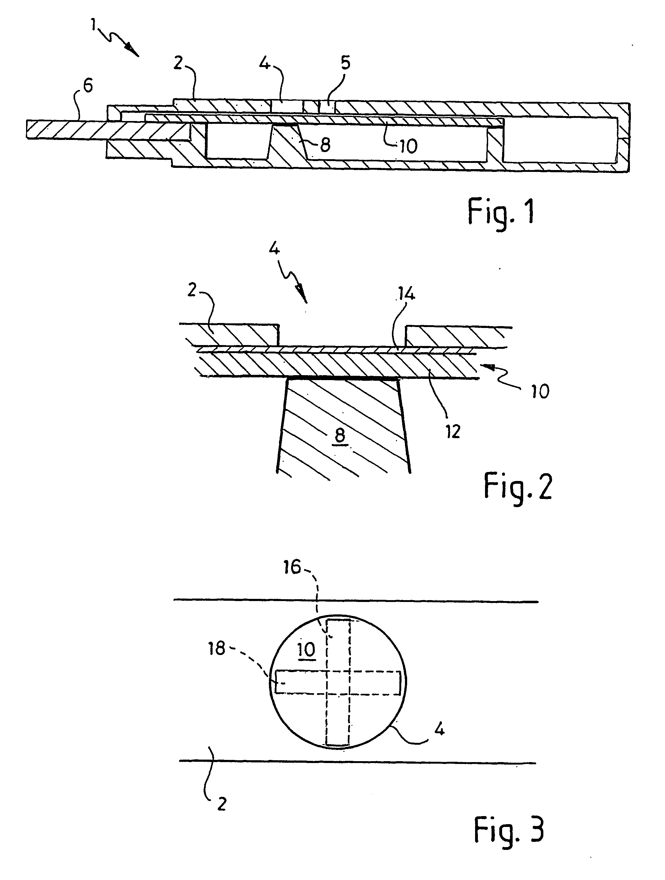
[0066]FIG. 1 is a cross section through an assay device 1 which measures urinary hCG, for use as a pregnancy test device. Assay device 1 comprises a case 2, made from a plastics material and having a result window 4 in the form of an aperture. A second aperture 5 through which a control signal generation means can be viewed is optional. A wick 6 protrudes from the case 2, for drawing up a liquid sample into the device, and a nitrocellulose strip 10 is in fluid communication with the wick 6. Case 2 has a protruberance 8 on an inner surface. Protruberance 8 presses against the nitrocellulose strip 10. FIG. 2 is an illustration of part of FIG. 1. This shows that the nitrocellulose strip 10 comprises an initially opaque porous nitrocellulose layer 12, backed by a transparent mylar layer 14.

[0067]FIG. 3 is a plan view of the assay device shown in FIG. 1 (but to a different scale to FIG. 1), showing that a portion of the nitrocellulose strip 10 is visible through result window 4. Initial...

example 2

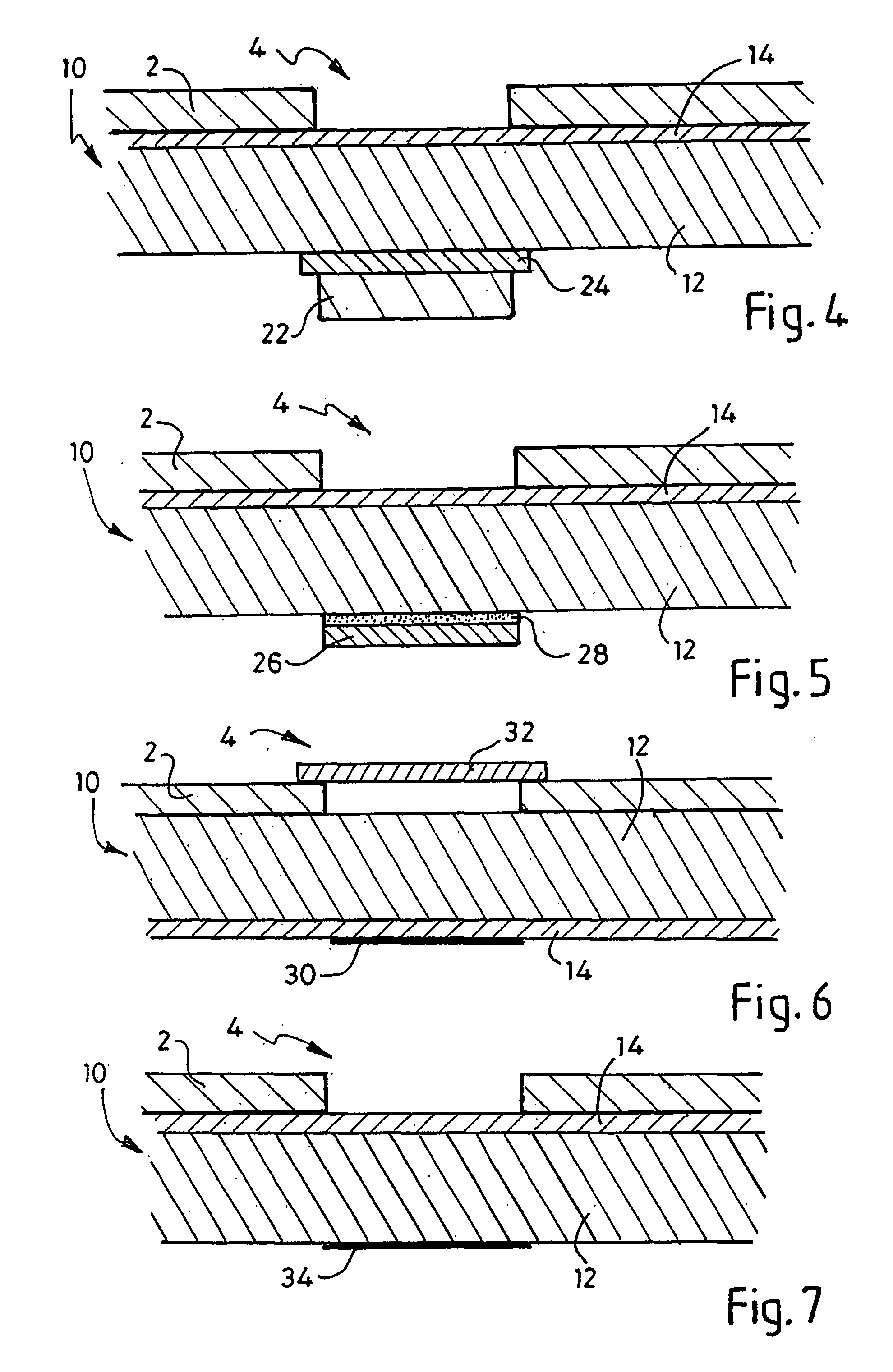
[0077]FIG. 4 illustrates an example embodiment of the assay device. In this embodiment, a printed mylar layer 24 is applied to the nitrocellulose strip, in contact with the porous nitrocellulose layer 12. It is held in place by a protruberance 22 supported by the case 2 of the assay device1. Conveniently, the use of a mylar strip 24 enables any type of image to be used merely by printing the image on the mylar strip with conventional printing technology.

example 3

[0078]FIG. 5 illustrates an alternative embodiment in which a visible image is applied to a mylar layer 26 by means of printing, and the mylar layer is held in contact with the porous nitrocellulose layer 12 by an adhesive layer 28. No protruberance is required in this example, but can optionally be provided.


PUM


Abstract

Disclosed is an assay device comprising liquid transport means adapted to take up a liquid sample and conduct the liquid to an analyte detection region operable to provide a test signal indicative of the presence and / or amount of an analyte in the liquid sample; the assay device further comprising a sample presence signal generation means, which is not generated by means of an immunoreaction. This sample presence signal generation means can comprise a coloured portion, which is overlaid by a material (e.g. nitrocellulose) that is opaque, when dry, and translucent or transparent, when wet, to allow the coloured portion to become visible to the user. In another embodiment the signal generation means comprises a colour changing material which under-goes a change in its visible properties upon wetting (eg. pH indication). A third embodiment uses a mobilisable detectable which, when wetted by the sample, is carried along resulting in a streaked line parallel with the flow direction.

Description

FIELD OF THE INVENTION [0001] The invention relates in general to the field of assay devices for measuring an analyte in a liquid sample and, more particularly, to such assay devices having a sample presence signal generation means. BACKGROUND TO THE INVENTION [0002] A number of assay devices for use in the measurement of one or more analytes in a liquid sample are known. Some of these are complex devices for use by trained personnel; for example, sampling devices for industrial liquids, water etc. or laboratory tests on blood, urine and the like. However, an important category of assay devices includes those intended for home use by consumers, for example home pregnancy test kits. Home pregnancy test kits typically function by determining the amount of the hormone human chorionic gonadotrophin (hCG) in a urine sample, and normally provide a visible indication as to whether a subject is pregnant. [0003] The specific example of the Clearblue test from Unipath, England (Clearblue is a...

Claims


Application Information

Patent Timeline
IPC IPC(8): C12Q1/00C12M1/34G01N33/543G01N33/558
CPCG01N33/54386G01N33/54306G01N33/558G01N33/54388
Inventor BREWSTER, BARRY SINCLAIRLESLIE, ADRIANDAVIES, ROBERT JOHN
Owner ABBOTT RAPID DIAGNOSTICS INT UNLTD
Why Eureka
Try Eureka