Micro optical sensor device

a sensor device and micro-optical technology, applied in the field of micro-optical sensor devices, can solve the problems of complex equipment or instrumentation, no commercial acceptance or viable, and typically requires a set up of relatively complex substances, etc., and achieves the effects of simple construction and design, high reliability, and easy us

Inactive Publication Date: 2006-02-09
RASKAS ERIC J
View PDF72 Cites 81 Cited by
  • Summary
  • Abstract
  • Description
  • Claims
  • Application Information

AI Technical Summary

Benefits of technology

[0009] In light of the foregoing comments, it will be recognized that a principal object of the present invention is to provide an improved sensor device which is hand held, portable, and easy to operate.
[0011] A further object of the present invention is to provide a sensor device which is of simple construction and design and which can be easily employed with highly reliable results.
[0012] Another object of the present invention is to provide a sensor device which is accurate and provides readings in a short time span.
[0013] A still further object of the present invention is to provide a sensor device which is compact in design and is easily transportable for personal use.

Problems solved by technology

Monitoring or detecting a concentration of a substance typically requires a set up of relatively complex, sensitive, and expensive equipment or instrumentation.
Additionally, such complex equipment may not provide results which are of a high resolution.
Since finger pricking or lancing is required for self monitoring levels of glucose in a patient, many patients avoid this because it is painful and inconvenient.
Although these devices use noninvasive methods, in that no blood is collected, none of these devices have been commercially accepted or viable.

Method used


Image

  • Micro optical sensor device
  • Micro optical sensor device
  • Micro optical sensor device

Examples


Embodiment Construction

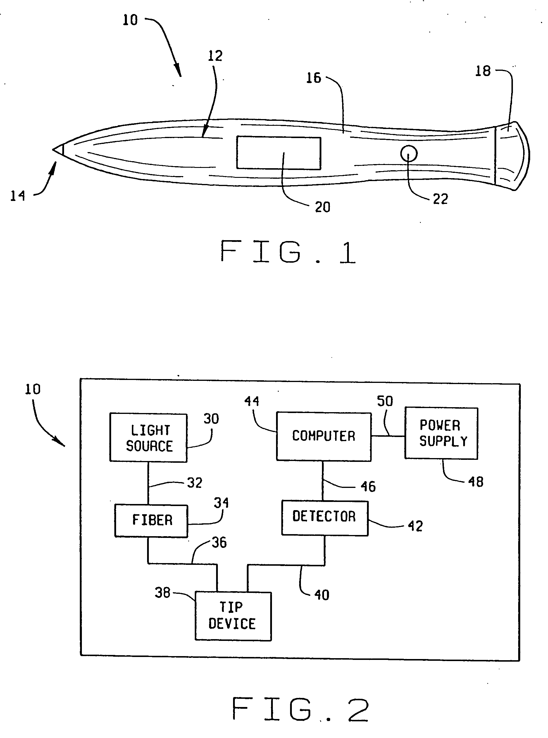
[0023] Referring now to the drawings, wherein like numbers refer to like items, number 10 identifies a preferred embodiment of a micro optical sensor device constructed according to the present invention. As illustrated in FIG. 1, the device 10 comprises a pencil or pen shaped body 12 which includes a tip portion 14, a central body portion 16, and an end cap 18. The central body portion 16 further includes a display device 20, such as an LED (light emitting diode) type display or an LCD type display, for displaying information. The end cap 18, which may be removable from the central body portion 16, is used to allow access into the interior of the central body portion 16. Batteries (not shown) can be inserted into the central body portion 16 to supply power to the device 10, as will be explained. The central body portion 16 may also include an ON / OFF switch 22 which may be used to operate the device 10. Other switches (not shown) may be incorporated into the central body portion 16 ...


PUM

PropertyMeasurementUnit
diameteraaaaaaaaaa
diameteraaaaaaaaaa
diameteraaaaaaaaaa

Abstract

A sensor device for measuring a concentration of a substance within a sample comprises a sensor comprising an optical transmission member having a first end and a second end, the second end having a tip portion attached thereto and an active material incorporated within the tip portion, the tip portion adapted to be inserted into a sample, the active material capable of interacting with a substance within a sample, a light source coupled to the first end of the sensor for emitting a beam of light into and through the sensor and into a sample, the emitted beam of light having a wavelength and the active material interacting with a substance within a sample to change the wavelength of the emitted beam of light to produce a reflected beam of light and the sensor for transmitting the reflected beam of light out of the second end thereof, an optical detector for receiving the reflected beam of light from the second end of the sensor for producing a signal indicative of the reflected beam of light, and a processor for receiving the signal indicative of the reflected beam of light and for processing the signal to determine the concentration of a substance within a sample.

Description

CROSS-REFERENCE TO RELATED APPLICATIONS [0001] This is a continuation-in-part of U.S. patent application Ser. No.09 / 729,611, filed on Dec. 4, 2000 which is a continuation of U.S. patent application Ser. No. 09 / 100,295 filed Jun. 19, 1998, now U.S. Pat. No. 6,157,442.BACKGROUND OF THE INVENTION [0002] This invention relates generally to a sensor device and more particularly to a micro optical sensor device which may be employed in a variety of sensor applications to monitor, sense, or measure a concentration of a material within a sample. [0003] There are numerous applications in which a device is used to monitor or detect a concentration of material within a substance. For example, it may be required to know the concentration of a chemical in a sample of material such as knowing the concentration of sodium, calcium, or some other chemical composition in a sample. Monitoring or detecting a concentration of a substance typically requires a set up of relatively complex, sensitive, and ...

Claims


Application Information

Patent Timeline
Patent Type & Authority Applications(United States)
IPC IPC(8): A61B5/00G01N33/543
CPCA61B5/14532G01N21/78G01N2400/00G01N33/5438G01N21/8507A61B5/1459B33Y80/00
Inventor RASKAS, ERIC J.
Owner RASKAS ERIC J
Why Eureka
Try Eureka