Vacuum lock

a vacuum lock and lock body technology, applied in the field of vacuum locks, can solve the problems of human operation, correspondingly dangerous conditions, and possible serious injury, and achieve the effect of high protection and safety

Inactive Publication Date: 2006-02-16
OC OERLIKON BALZERS AG
View PDF11 Cites 22 Cited by
  • Summary
  • Abstract
  • Description
  • Claims
  • Application Information

AI Technical Summary

Benefits of technology

[0004] The present invention has as its aim to eliminate the disadvantages of the above described prior art. The aim comprises in particular realizing an economically realizable vacuum lock with a sliding gate disposed substantially vertically, which, if a person accidentally reaches into the gate opening, offers a high degree of protection and safety for this person.
[0007] The gate is herein developed as a plate-form sliding gate, which, for the purpose of opening and closing the gate opening, is disposed parallel to the plane of the gate opening and slightly spaced apart from the gate opening. The gate is operatively connected with a driving rod and a drive on the side facing away from the gate opposite the gate opening. This gate is supported in the sliding direction and supported opposing the gate opening at a specified distance. The driving rod is connected with the gate via a guidance mechanism, such as for example a short lever, which can change or deflect the direction of the movement of the gate, such that in the presence of a blockage of the closing process through a hindrance and / or a limitation in the proximity of the gate opening, the gate is laterally pressed against a seal encompassing the gate opening in the vertical direction with respect to the plane of the gate opening. The driving rod is connected with the gate and / or the driving rod-side guidance mechanism with a spring element such that the spring narrowly compensates or bears the weight of the gate. In this way the gate is resiliently and movably disposed on the driving rod and can be slid with respect to the driving rod in the vertical direction about the spring path determined by the spring element.

Problems solved by technology

The closing process of the lock gate which thereupon becomes necessary, represents a considerable injury potential for this operation carried out by human personnel.
A defect of the closure system or also an erroneous behavior by the operator can cause correspondingly dangerous conditions and possibly serious injury.
As a rule, such systems are complex and expensive and usually do not include the desired high degree of safety, since electronic systems themselves can also be prone to errors.

Method used


Image

  • Vacuum lock
  • Vacuum lock
  • Vacuum lock

Examples


Embodiment Construction

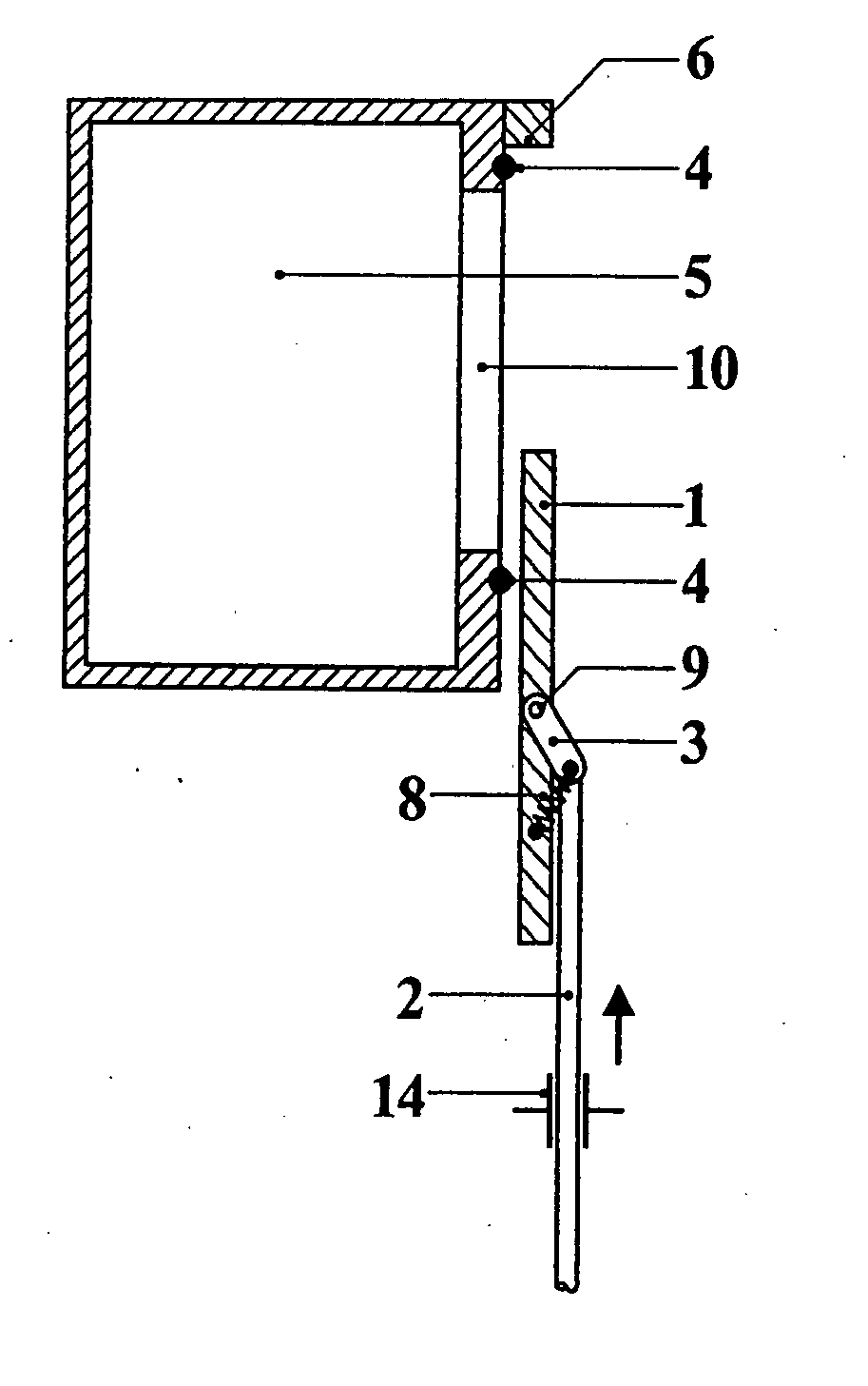
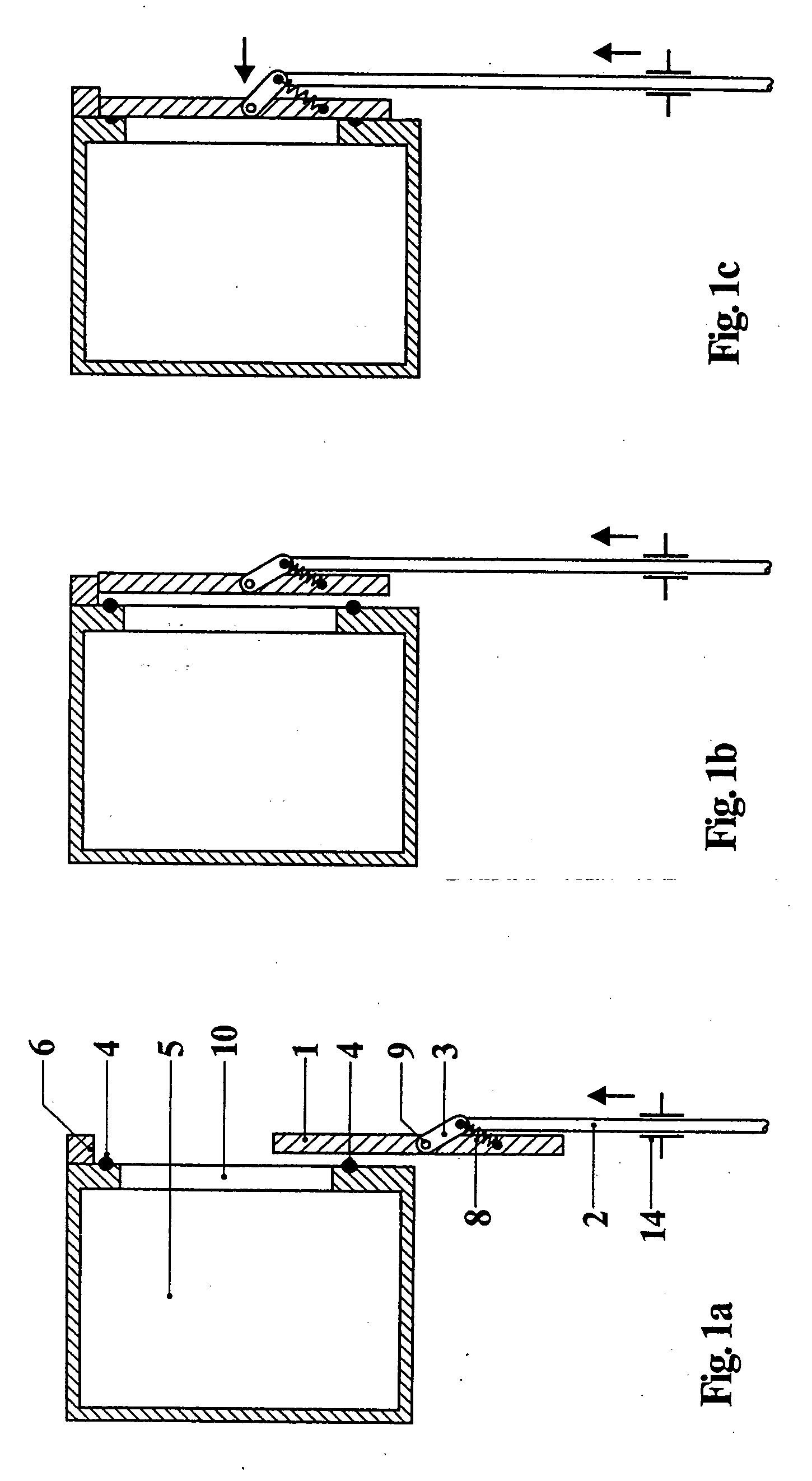
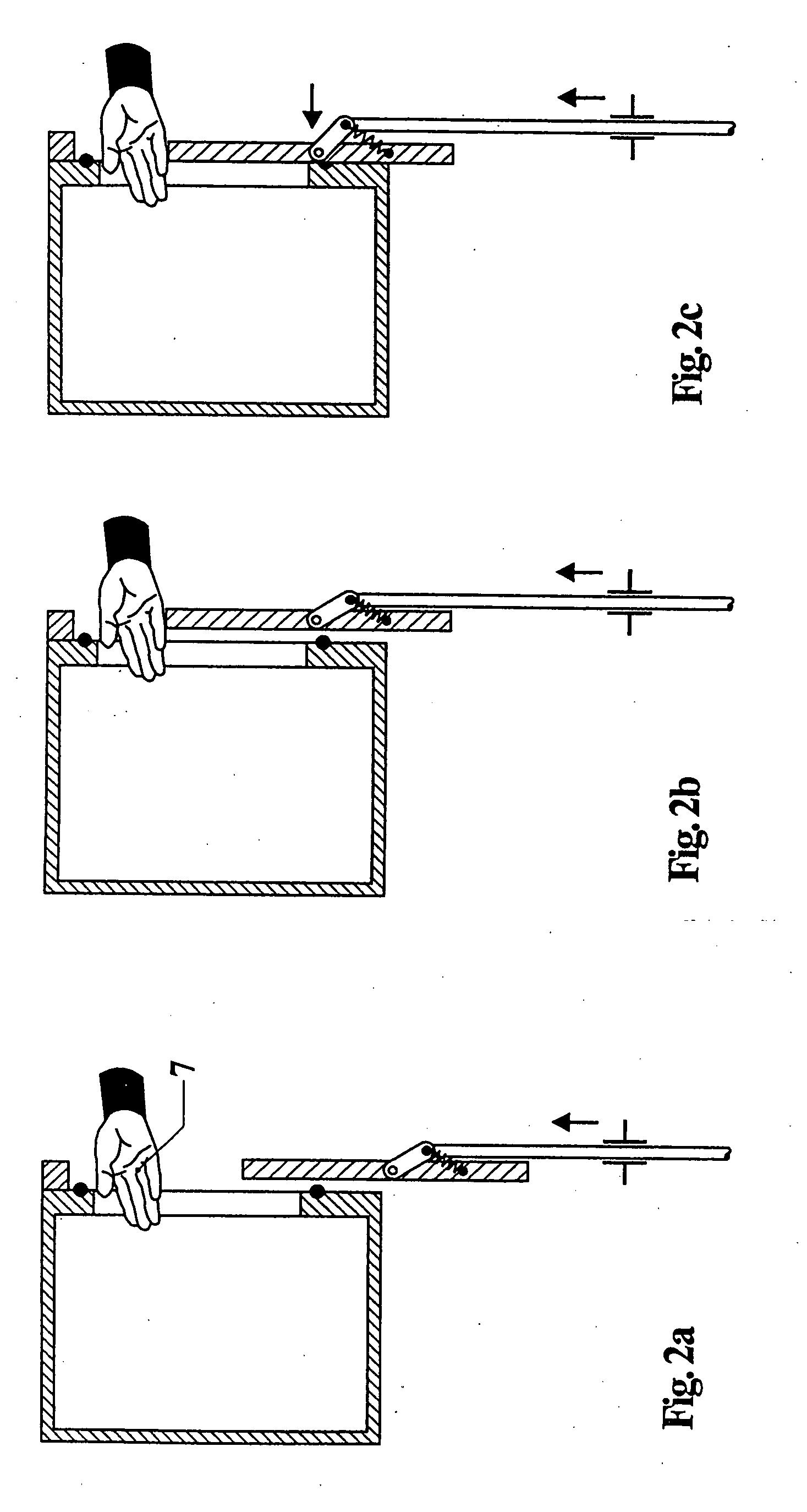
[0024] In the figures preferred embodiments of lock configurations according to the invention are depicted schematically and in section. FIG. 1a shows a lock chamber 5 with a sliding gate 1 in the open state. The chamber 5 comprises an opening 10, which with a seal 4 is disposed on the outer surface of the chamber 5 in order to be able to seal in the closed state the outer region of the chamber against the inner region. Vacuum chambers as well as also the associated lock gates in vacuum applications are, as a rule, comprised of metal such as aluminum or stainless steel. The gate 1 consists of a plate, which is supported such that it can be slid parallel to the plane of the gate opening 10 and be moved in any position in the lateral direction against the seal vertically with respect to the gate opening 10 and can, consequently, be pressed against the seal. The distance of the gate 1 with respect to the surface of the chamber wall or the gate opening 10 is conventionally a few millime...


PUM


Abstract

A vacuum lock on a vacuum chamber has a lockable gate opening with a substantially vertical gate and the following characteristics: the gate is a sliding plate displaceable parallel to the opening; the gate is connected via a driving rod on a side oppose the opening and is supported at a distance in the sliding direction; this connection is via a guidance mechanism such that in the presence of a blockage of the closing process, the gate is laterally pressed on a seal encompassing the opening; and a spring element is provided to narrowly compensates the weight of the gate. This ensures that in the event of a operator error or unintentional reaching into the opening during a closing process, injuries cannot occur and a high degree of safety is ensured.

Description

FIELD AND BACKGROUND OF THE INVENTION [0001] The invention relates to a vacuum lock disposed in a vacuum chamber with a gate opening, disposed substantially vertically and in one plane lockable with a gate, as well as to a method for transporting substrates through the lock into a vacuum chamber. [0002] In automated vacuum process units vacuum locks or valves are utilized for passing substrates to be worked from one atmosphere into the other, such systems, as a rule, being operated pneumatically or electrically. Many such systems utilize gates which are developed as sliding gates, which are slid along a vacuum seal disposed about a gate opening and subsequently is pressed on for sealing. When the sliding gate is open, substrates or also entire cassettes with substrates, for example with semiconductor wafers, can be placed into the vacuum chamber. This introduction of substrates into a vacuum chamber through a lock gate opening is often carried out manually and human personnel extend...

Claims


Application Information

Patent Timeline
Patent Type & Authority Applications(United States)
IPC IPC(8): F16K35/00B01J3/03B01L1/02F16J13/24
CPCB01J3/03B01L1/02H01L21/67126F16J13/24F16J13/22F16K3/182F16K3/184
Inventor VAN MAST, BART SCHOLTEJAEGER, SILVIO
Owner OC OERLIKON BALZERS AG
Why Eureka
Try Eureka