Constrained layer damping assembly

a damping assembly and tensioning technology, applied in the direction of shock absorbers, machine supports, mechanical equipment, etc., can solve the problems of high energy loss, and achieve the effect of minimizing the amplitude of resonant vibration

Inactive Publication Date: 2006-02-16
GUZIK TECHN ENTERPRISES
View PDF7 Cites 19 Cited by
  • Summary
  • Abstract
  • Description
  • Claims
  • Application Information

AI Technical Summary

Benefits of technology

[0005] The present invention provides a constrained layer damping assembly for minimizing the amplitude of resonant vibration. The constrained layer damping assembly is positioned over a surface of a device body, for example, a top surface of a rigid structure, when in use. The damping assembly comprises a substantially gas impervious damping layer, which overlies at least a portion of the top surface, and an inertial mass (e.g., a load element) disposed on the damping layer. The constrained damping layer assembly further includes means for positioning the load element with respect to the top surface of the rigid structure while maintaining the damping layer in compression. The positioning means preferably includes at least one void region passing through the damping layer from the top surface of the rigid structure to the bottom surface of the load element, and means for coupling a low pressure to the void region relative to the pressure external to the constrained layer damping assembly. In one preferred embodiment, the constrained damping layer defines two void regions, and the load element defines two vacuum channels respectively associated with the two void regions for coupling the void regions to an external vacuum. In alternative forms, the two vacuum channels may be defined passing through the device body or the damping layer, coupling the void regions to the external vacuum. The vacuum, via the channels, keeps the pressure in the void regions at a relative low value to establish a pressure differential across the load element. The pressure differential provides a force, which keeps the damping layer under compression, and secures the load element and the damping layer to the top surface of the rigid structure.

Problems solved by technology

When these materials are deformed, internal friction causes high energy losses to occur.
One disadvantage of the prior art assembly shown in FIG. 1 is that the bolt 29A used for coupling plates 24 and 26 together is made of a rigid material with low loss factor, for example, steel, for effecting a secure connection.

Method used


Image

  • Constrained layer damping assembly
  • Constrained layer damping assembly
  • Constrained layer damping assembly

Examples


Embodiment Construction

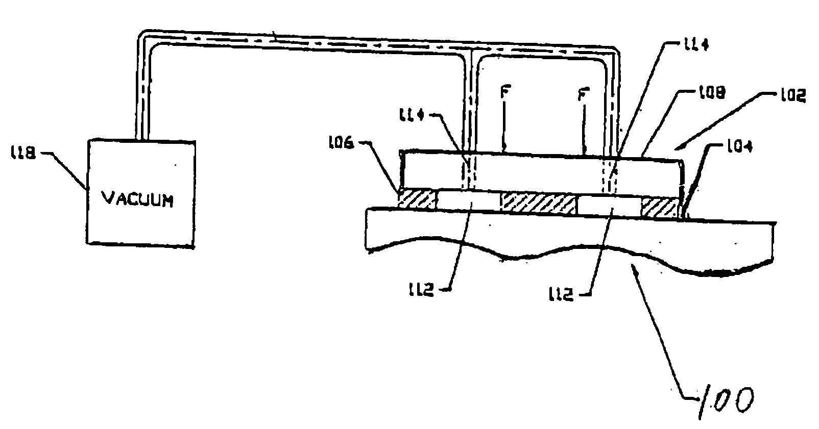
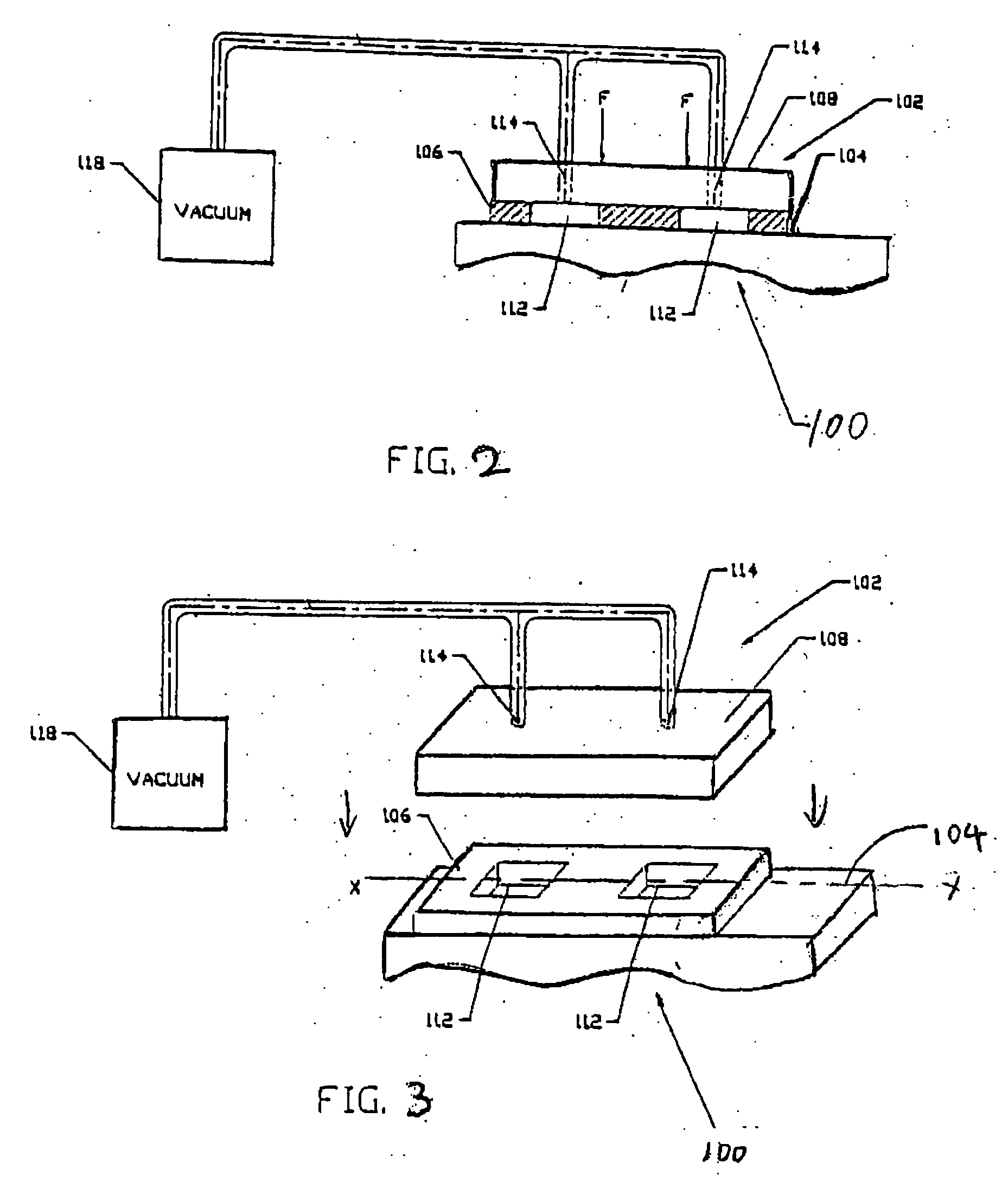
[0016] The invention will now be further described in detail with reference to the following preferred embodiments. FIG. 2 illustrates a cross-sectional view and FIG. 3 illustrates an exploded view of a constrained layer damping assembly 102 according to one preferred embodiment of the present invention. The assembly 102 is positioned on a top surface 104 of a device body 100. It should be understood that the constrained layer damping assembly 102 can be used with any surfaces of any devices where a vibration damping is desired.

[0017] The damping assembly 102 is formed by at least a portion of the top surface 104 of the device body 100, a substantially gas impervious damping layer 106, which overlies at least a portion of the top surface 104, and an inertial mass (e.g., a load element) 108 disposed on the damping layer 106. The top surface 104 is preferably planar and extends along a reference axis X. The load element 108 is preferably rigid.

[0018] The constrained layer damping as...


PUM


Abstract

A constrained layer damping assembly for a rigid base member having a substantially planar surface comprises a gas impervious damping layer disposed on the substantially planar surface of the base member, and a load element disposed on the damping layer. The damping layer defines at least one void region extending between the planar surface and the load element, and the load element defines at least one channel for coupling a low pressure to the void region relative to the pressure external to the constrained layer damping assembly to establish a pressure differential between the inside of the void region and the outside of the constrained layer damping assembly. The pressure differential keeps the damping layer under compression and secures the load element and the damping layer onto the base member.

Description

FIELD OF THE INVENTION [0001] The present invention relates damping assemblies for mechanical structure, in particular, to constrained layer damping assemblies. BACKGROUND OF THE INVENTION [0002] In the prior art, damping is used to reduce the amplitude of resonant vibration in mechanical assemblies by converting a portion of the energy into low-grade heat, often with the use of elastomeric materials. Typically, such vibration damping materials use a mechanism known as hysteretic damping to dissipate energy. When these materials are deformed, internal friction causes high energy losses to occur. [0003]FIG. 1 shows a prior art vibration damping assembly as applied to two rigid plates 24 and 26. As shown in FIG. 1, an elastomeric isolation mount as denoted by number 29, is placed between the rigid plate members 24 and 26 to absorb vibratory energy in the plates. A bolt 29A and nut 29B couple the plates 24 and 26 together while maintaining the isolation mount 29 under compression. The ...

Claims


Application Information

Patent Timeline
Patent Type & Authority Applications(United States)
IPC IPC(8): F16F15/00
CPCF16F15/027F16F9/306
Inventor GUZIK, NAHUMST. DENNIS, MICHAEL CHRISTOPHER
Owner GUZIK TECHN ENTERPRISES
Why Eureka
Try Eureka