Positioning device
a positioning device and positioning technology, applied in the direction of metal working apparatus, metal-working machine components, manufacturing tools, etc., can solve the problem of reducing positioning accuracy and gap, and achieve the effect of reliable and highly accurate positioning
- Summary
- Abstract
- Description
- Claims
- Application Information
AI Technical Summary
Benefits of technology
Problems solved by technology
Method used
Image
Examples
first embodiment
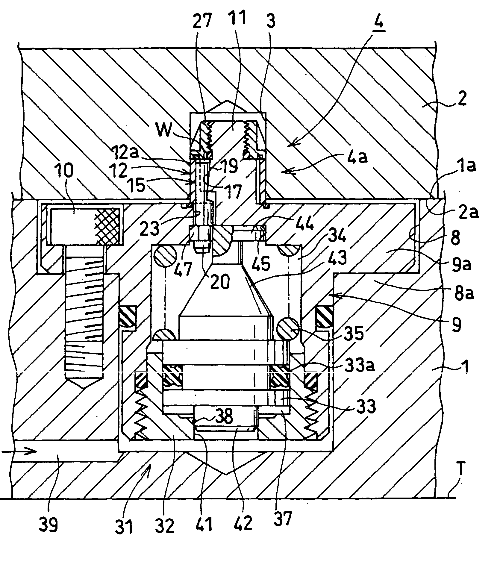
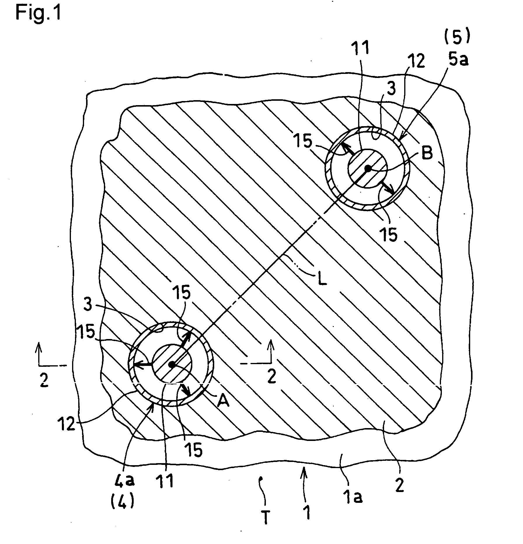
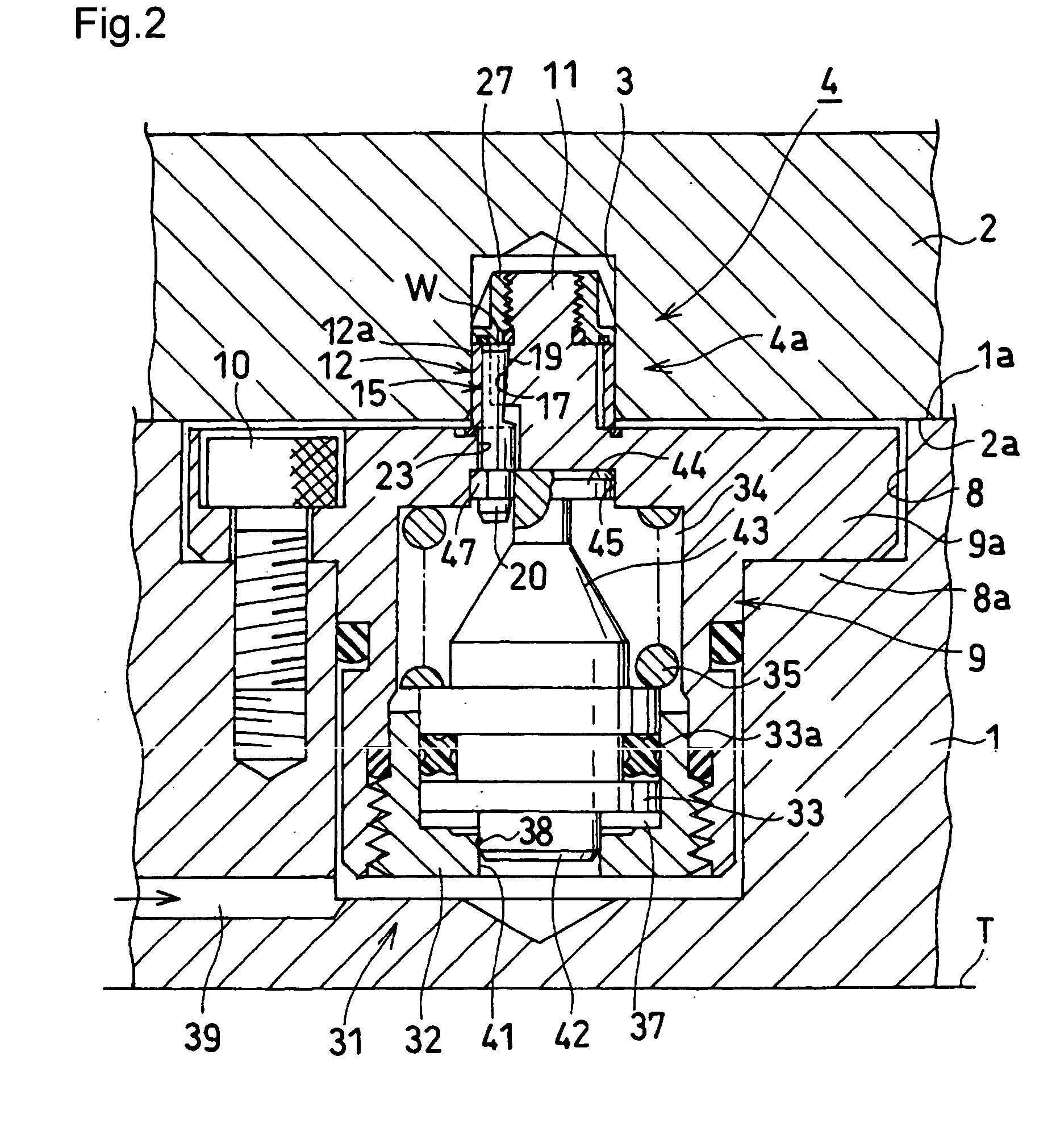
[0097]FIG. 1 through 5 show an example in which a positioning apparatus according to the present invention is applied to a pallet system as a The entire structure of the pallet system will first be described with reference to FIGS. 1 and 2. FIG. 1 is a view typically showing the basic principle of the pallet system, and particularly a horizontal cross-sectional view of the pallet system. Also, FIG. 2 is an elevational cross-sectional view of the positioning apparatus in a released state, corresponding to a view indicated by the arrow 2-2 in FIG. 1.
[0098] In this embodiment, a base plate 1 as a first block is placed on a table T of a machine tool, and it is arranged that a surface 2a to be supported of a work pallet 2 as a second block is supported onto a support surface 1a of the base plate 1, and that the work pallet 2 is aligned to the base plate 1.
[0099] In the surface 2a to be supported of the work pallet 2 are opened a plurality of precisely processed engaging holes 3. There ...
second embodiment
[0142]FIG. 12 is a view similar to FIG. 3A, showing the In this case, the wedge spaces W and the wedge members 15 are formed in such a manner as to narrow upward (toward the leading end). The lock chamber 34 is formed under the piston 33. The lower part of an upper rod 43 projected upward from the piston 33 is sealed by means of a packing 65, and the release chamber 37 is formed on the outer periphery of the upper rod 43. Then, in a locking operation, the piston 33 is driven upward by the lock spring 35 provided in the lock chamber 34. Then, the output portion 44 provided in the upper part of the upper rod 43 moves the plurality of wedge members 15 upward, and the wedge members 15 expand the elastic sleeve 12 radially.
[0143] It is noted that in the outer peripheral surface of the central pillar 11 may be arranged inclined grooves, which are inclined downward, circumferentially at substantially the same intervals instead of being formed a tapered surface 55 which narrow downward, as...
third embodiment
[0144]FIG. 13 is a view similar to FIG. 3A, showing the In this case, the driving means 31 comprises a spring support 67 inserted in the housing 9 of the base plate 1, an operation bolt 68 supported in the central pillar 11 rotatably and screwed into the spring support 67, and the lock spring 35 for urging the spring support 67 downward. The spring support 67 is prevented from rotating centering on the axial center thereof by means of a pin 69.
[0145] In the released state shown in the figure, the operation bolt 68 is rotated and tightened using a hexagonal wrench (not shown in the figure) inserted in an operation hole 70 of the work pallet 2. Thus, the spring support 67 is moved up against the lock spring 35, and the wedge members 15 are moved upward to be released by the output portion 44 provided in the upper part of the spring support 67. When switching from the released state to a locked state, the operation bolt 68 is rotated and loosened. Then, the spring support 67 is moved ...
PUM
 Abstract
Description
Claims
Application Information
 - R&D
- Intellectual Property
- Life Sciences
- Materials
- Tech Scout
- Unparalleled Data Quality
- Higher Quality Content
- 60% Fewer Hallucinations
Browse by: Latest US Patents, China's latest patents, Technical Efficacy Thesaurus, Application Domain, Technology Topic, Popular Technical Reports.
© 2025 PatSnap. All rights reserved.Legal|Privacy policy|Modern Slavery Act Transparency Statement|Sitemap|About US| Contact US: help@patsnap.com


