Arrangment for giving planar antenna added strength in construction

Inactive Publication Date: 2006-02-16
EMTAC TECH CORP
View PDF5 Cites 55 Cited by
  • Summary
  • Abstract
  • Description
  • Claims
  • Application Information

AI Technical Summary

Benefits of technology

[0006] It is an object of the present invention to integrally form two supports with the radiating metal member and bend, extend downward same therefrom. The supports are served as feed point and ground terminal respectively. By utilizing this arrangement added strength

Problems solved by technology

The feed posts 131 and 132 are formed in the planar antenna by soldering and wh

Method used


Image

  • Arrangment for giving planar antenna added strength in construction
  • Arrangment for giving planar antenna added strength in construction
  • Arrangment for giving planar antenna added strength in construction

Examples


Embodiment Construction

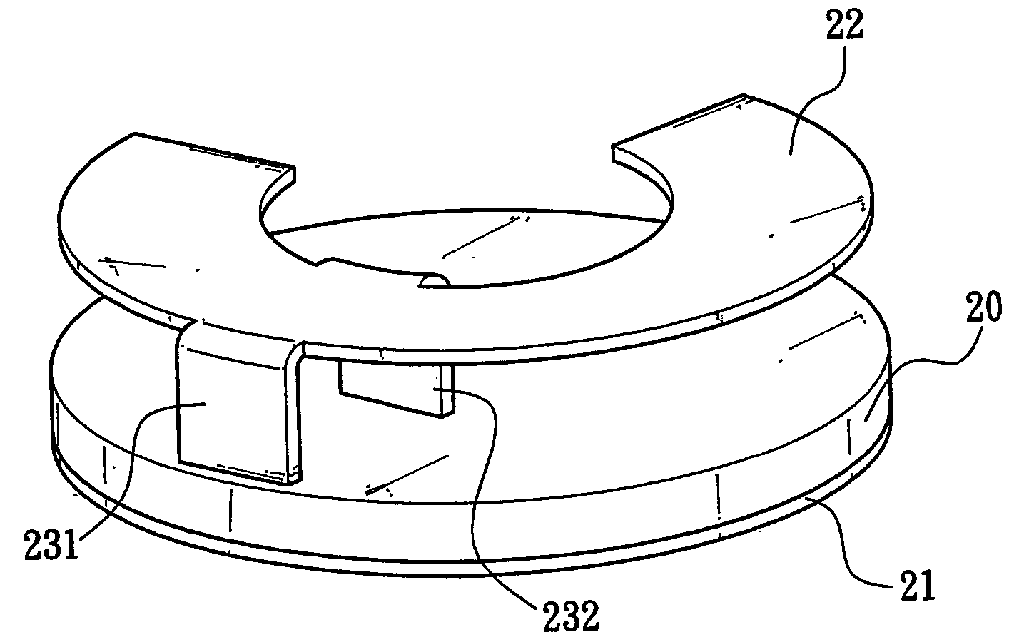
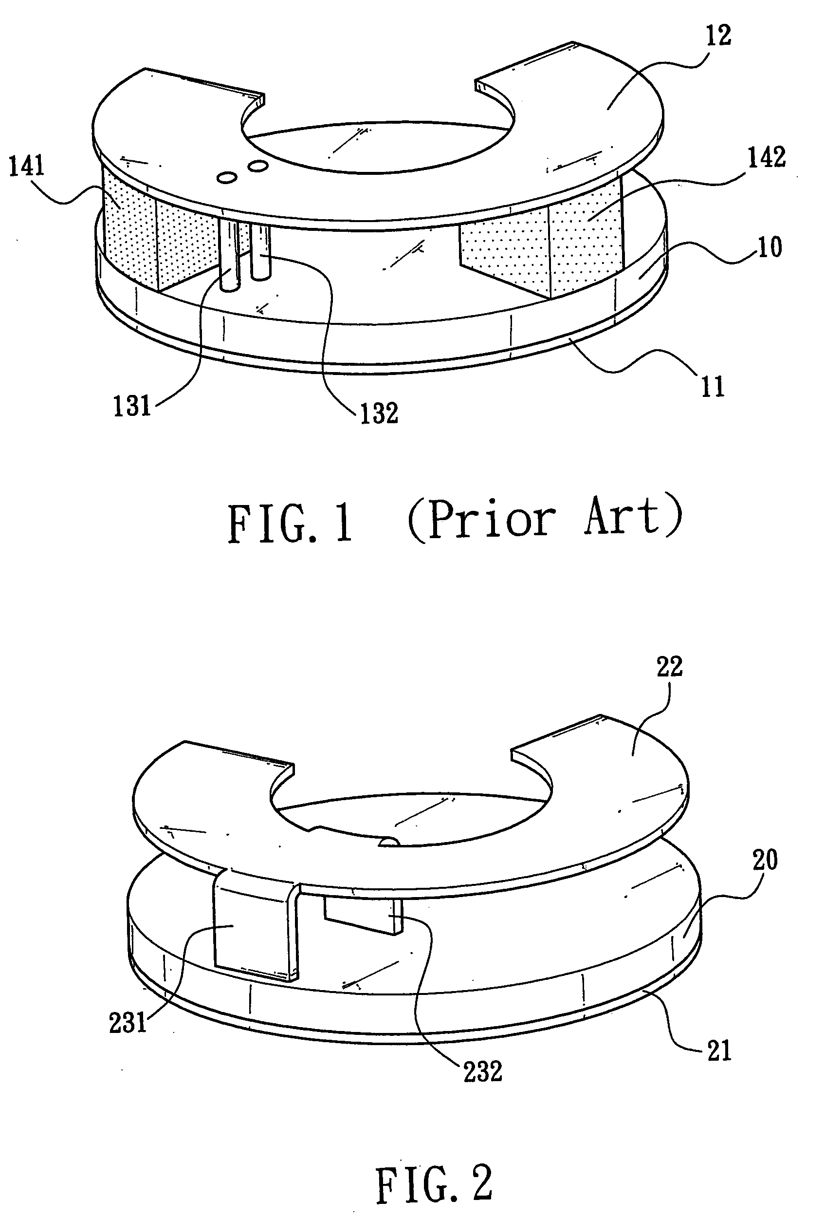
[0012] Referring to FIG. 2, there is shown a first preferred embodiment of planar antenna according to the invention. The planar antenna is adapted to operate in many different bands and the planar antenna is preferably implemented as a PIFA (planar inverted-F antenna) for a GSM or PDC based cellular phone as detailed below.

[0013] Referring to FIG. 2, the PIFA is adapted to operate in dual-band by configuring as a single feed double path antenna. The PIFA comprises a disk-shaped dielectric substrate 20 formed of resin, a grounded metal element 21 on bottom of the dielectric substrate 20, the grounded metal element 21 being formed by photolithography and etching, and a curved radiating metal member 22 above the dielectric substrate 20, the radiating metal member 22 being formed by punching and having two free ends, the radiating metal member 22 including two radial supports 231 and 232 in its intermediate portion, the supports 231 and 232 being bent and extended downward wherein the...


PUM


Abstract

The present invention is to provide an arrangement for giving a planar antenna added strength in construction, which comprises a grounded metal element on bottom of a dielectric substrate of the planar antenna and a curved radiating metal member above the dielectric substrate including two integral radial supports bent and extended downward, wherein one support has one end electrically connected to circuitry in the dielectric substrate for serving as a feed point, and the other support has one end passed the dielectric substrate to connect to the grounded metal element for serving as a ground terminal, so as to prevent the planar antenna from being easily deformed.

Description

FIELD OF THE INVENTION [0001] The present invention relates to planar antennas, more particularly to an arrangement for giving a planar antenna added strength in construction by integrally forming two supports on a radiating metal member of the planar antenna as feed point and ground terminal respectively, so as to add strength to the construction of the planar antenna and prevent it from being easily deformed. BACKGROUND OF THE INVENTION [0002] A conventional planar antenna mounted in a GSM (Global System for Mobile Communications) based or PDC (personal digital cellular) based cellular phone is shown in FIG. 1. The planar antenna comprises a disk-shaped dielectric substrate 10 formed of resin, a grounded metal element 11 on bottom of the dielectric substrate 10, the grounded metal element 11 being formed by photolithography and etching, and a curved radiating metal member 12 above the dielectric substrate 10, the radiating metal member 12 having two radial feed posts 131 and 132 i...

Claims


Application Information

Patent Timeline
IPC IPC(8): H01Q1/38H01Q1/48H01Q9/04H01Q9/14
CPCH01Q9/0414
Inventor YANG, PEI-LIN
Owner EMTAC TECH CORP
Why Eureka
Try Eureka