Liquid crystal display mounted with IC tag and method for manufacturing the same
a technology of liquid crystal display and ic tag, which is applied in the direction of electric digital data processing, instruments, computing, etc., can solve the problems of inability to read data from the intensity of the radio wave from the antenna fluctuating, and the inability to paste the wireless ic tag onto the small-size liquid crystal display, etc., to achieve the effect of increasing the size of the liquid crystal display, enhancing the intensity of radio wave from the antenna, and increasing the length of the antenna
- Summary
- Abstract
- Description
- Claims
- Application Information
AI Technical Summary
Benefits of technology
Problems solved by technology
Method used
Image
Examples
embodiment 1
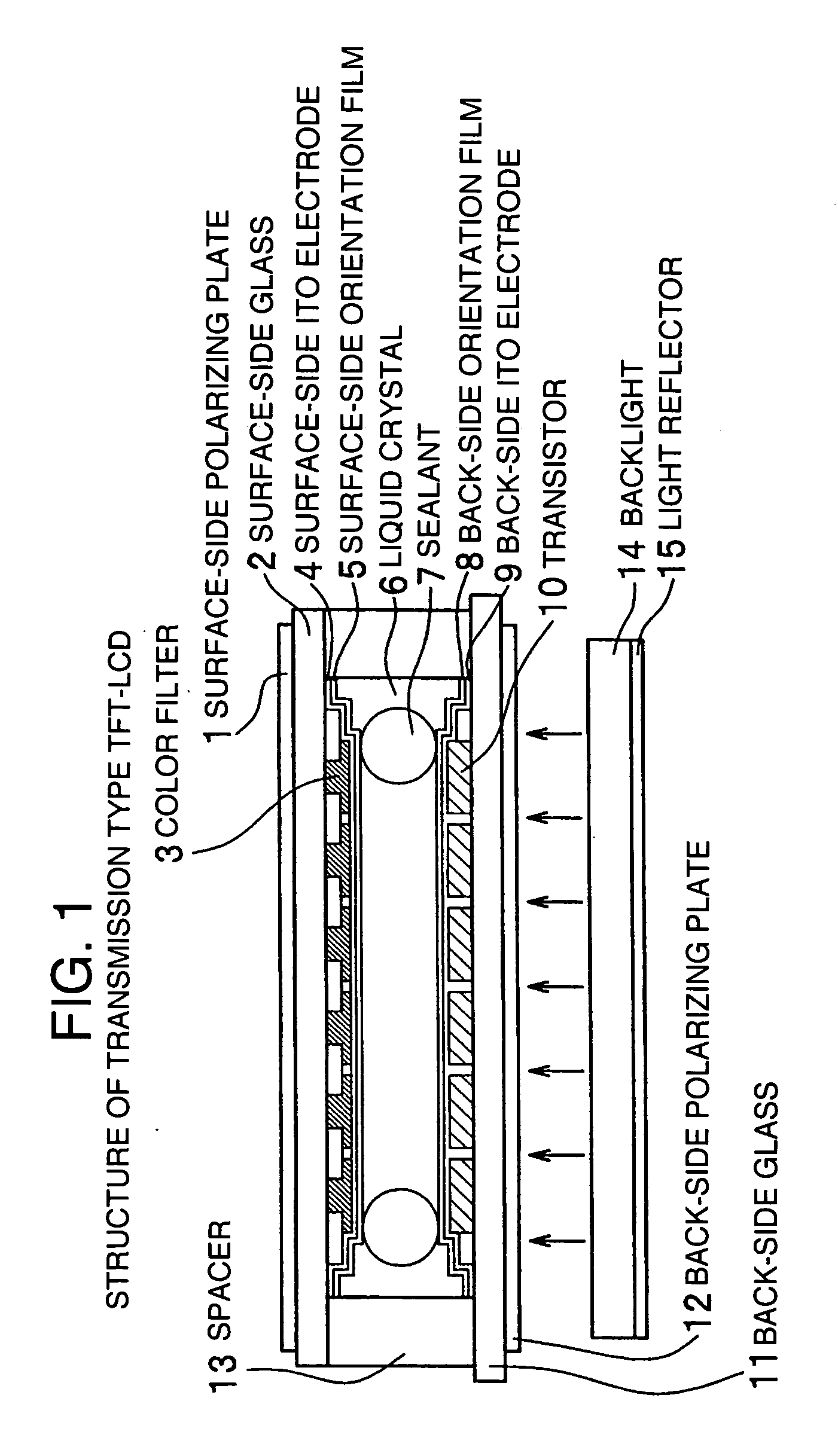
[0039] In Embodiment 1, description will be made about a method for mounting a wireless IC tag, in which an antenna and a wireless IC tag are mounted on an active matrix type liquid crystal display having X-axis electrodes and Y-axis electrodes formed only in a lower electrode layer in a transmission type TFT-LCD shown in FIG. 1. Embodiment 1 has some variations as to the position where the antenna is formed. Of the variations, typical variations will be described.
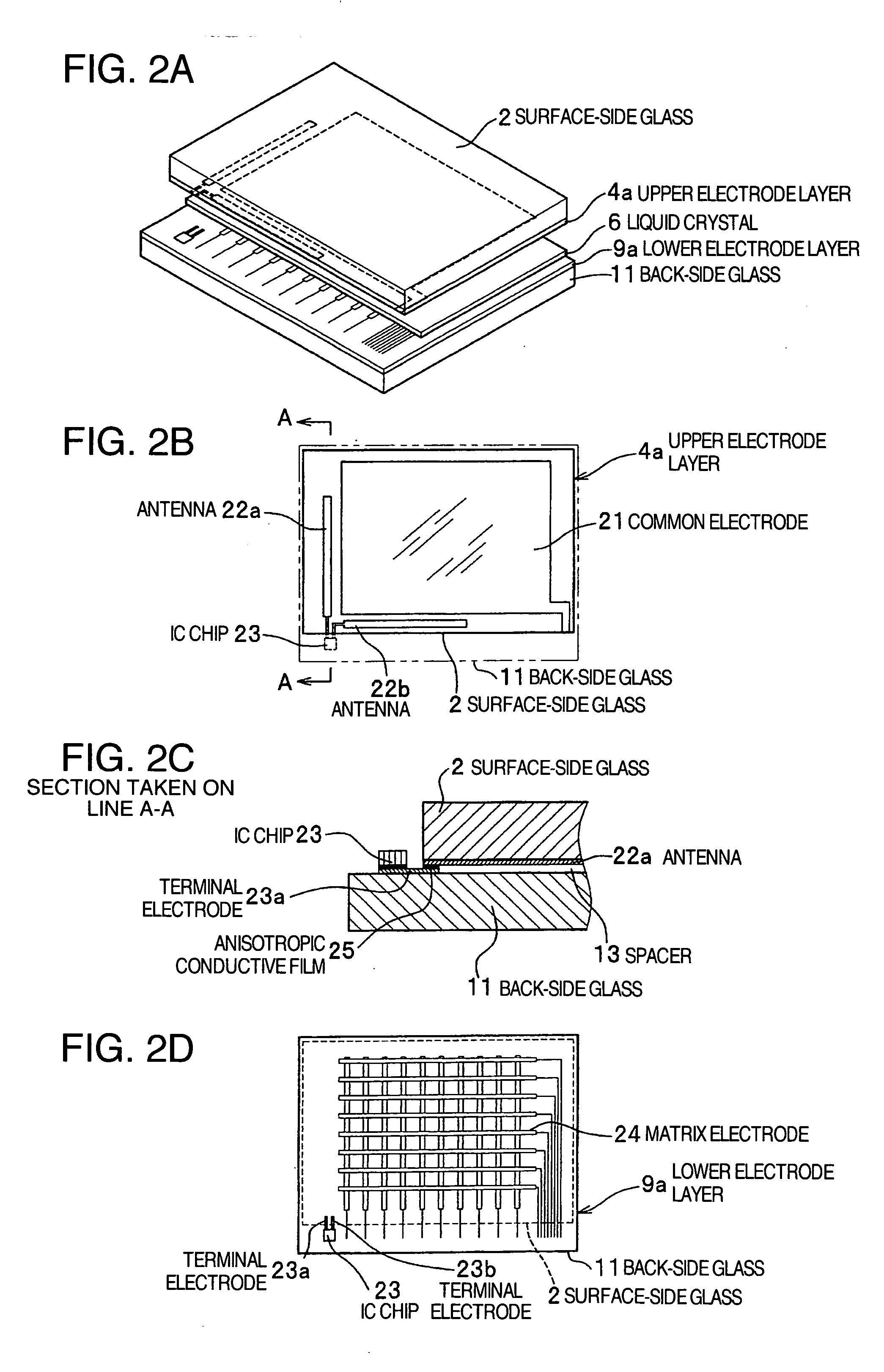
[0040] First, description will be made about Variation 1 of Embodiment 1 in which a wireless IC tag is mounted on an active matrix type liquid crystal display. FIGS. 2A-2D are conceptual diagrams of Variation 1 in Embodiment 1 of the present invention in which a wireless IC tag is mounted on an active matrix type liquid crystal display. FIG. 2A shows a laminated configuration of the liquid crystal display. FIG. 2B shows an upper electrode layer. FIG. 2C shows a partial section taken on line A-A in FIG. 2B. FIG. 2D shows a...
embodiment 2
[0066] In Embodiment 2, description will be made about a method for mounting a wireless IC tag, in which each antenna and an IC chip are mounted on a passive matrix type liquid crystal display having X-axis electrodes formed in an upper electrode layer and Y-axis electrodes formed in a lower electrode layer. Embodiment 2 also has some variations as to the position where the antenna is formed. Of the variations, typical variations will be described here.
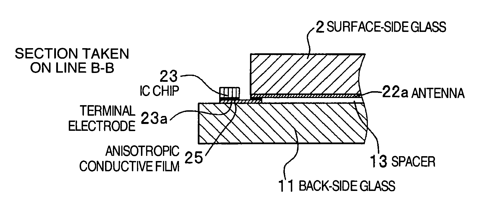
[0067] First, description will be made about Variation 1 of Embodiment 2 in which a wireless IC tag is mounted on a passive matrix type liquid crystal display. FIGS. 11A-11D are conceptual diagrams of Variation 1 in Embodiment 2 of the present invention in which a wireless IC tag is mounted on a passive matrix type liquid crystal display. FIG. 11A shows a laminated configuration of the liquid crystal display. FIG. 11B shows an upper electrode layer. FIG. 11C shows a partial section taken on line B-B in FIG. 11B. FIG. 11D shows a lowe...
embodiment 3
[0075] Next, description will be made about Embodiment 3 in which a wireless IC tag is mounted on a liquid crystal display having a light reflector. FIGS. 15A-15B are conceptual diagrams showing Embodiment 3 of the present invention in which a wireless IC tag is mounted on a liquid crystal display having a light reflector. FIG. 15A shows a sectional view of the liquid crystal display, and FIG. 15B shows a plan view of the liquid crystal display. As shown in FIG. 15A, the liquid crystal display has a laminated configuration of a surface-side glass 2, an upper electrode layer 4a, a liquid crystal 6, a lower electrode layer 9a, a back-side glass 11 and a light reflector 33. In the liquid crystal display configured thus, as shown in FIG. 15B, an antenna 22 is connected to one terminal of an IC chip 23, while the light reflector 33 is connected to the other terminal of the IC chip 23 so that the light reflector 33 can serve as a radiation surface of the antenna. In this case, it is desir...
PUM
 Abstract
Description
Claims
Application Information
 - R&D
- Intellectual Property
- Life Sciences
- Materials
- Tech Scout
- Unparalleled Data Quality
- Higher Quality Content
- 60% Fewer Hallucinations
Browse by: Latest US Patents, China's latest patents, Technical Efficacy Thesaurus, Application Domain, Technology Topic, Popular Technical Reports.
© 2025 PatSnap. All rights reserved.Legal|Privacy policy|Modern Slavery Act Transparency Statement|Sitemap|About US| Contact US: help@patsnap.com


