Spatially distributed spectrally neutral optical attenuator

a spectrally neutral, optical attenuator technology, applied in the field of surgical instruments, can solve the problems of non-homogeneous attenuation across the cross-section of the light beam, non-equal attenuation of modes (angles), and ring structures appearing in the beam output focal spo

Inactive Publication Date: 2006-02-16
ALCON INC
View PDF5 Cites 7 Cited by
  • Summary
  • Abstract
  • Description
  • Claims
  • Application Information

AI Technical Summary

Benefits of technology

[0013] A more complete understanding of the present invention and the advantages thereof may be acquired by referring to the following description, taken in conjunction with the accompanying drawings, in which like reference numbers indicate like features and wherein:
[0014]FIG. 1 is a simplified block diagram illustrating an exemplary high-brightness illuminator system 10 comprising an embodiment of the present invention;
[0015]FIG. 2 is a simplified block diagram illustrating in greater detail an embodiment of an optical attenuator according to the present invention;
[0016]FIG. 3 is a simplified drawing of an exemplary stamping tool for shaping a fin-plate of an embodiment of an optical attenuator of this invention;

Problems solved by technology

This non-homogeneous attenuation across the cross-section of the light beam, however, is not desirable in many applications, in particular in systems that focus light into multimode fibers, as it can result in different modes (angles) being attenuated in a non-equal manner.
This can result in ring structures appearing in the beam output focal spot.
Other prior art small scale attenuators used in ophthalmic illumination systems are disclosed in U.S. Pat. No. 6,404,970 to Gransden et al., and U.S. Pat. No. 6,367,958 and U.S. Pat. No. 5,006,965 to E. M. Jones. These prior art attenuators, however, do not provide color neutrality, compact size, a direct motor drive or homogeneous attenuation across the entire light aperture.

Method used


Image

  • Spatially distributed spectrally neutral optical attenuator
  • Spatially distributed spectrally neutral optical attenuator
  • Spatially distributed spectrally neutral optical attenuator

Examples


Embodiment Construction

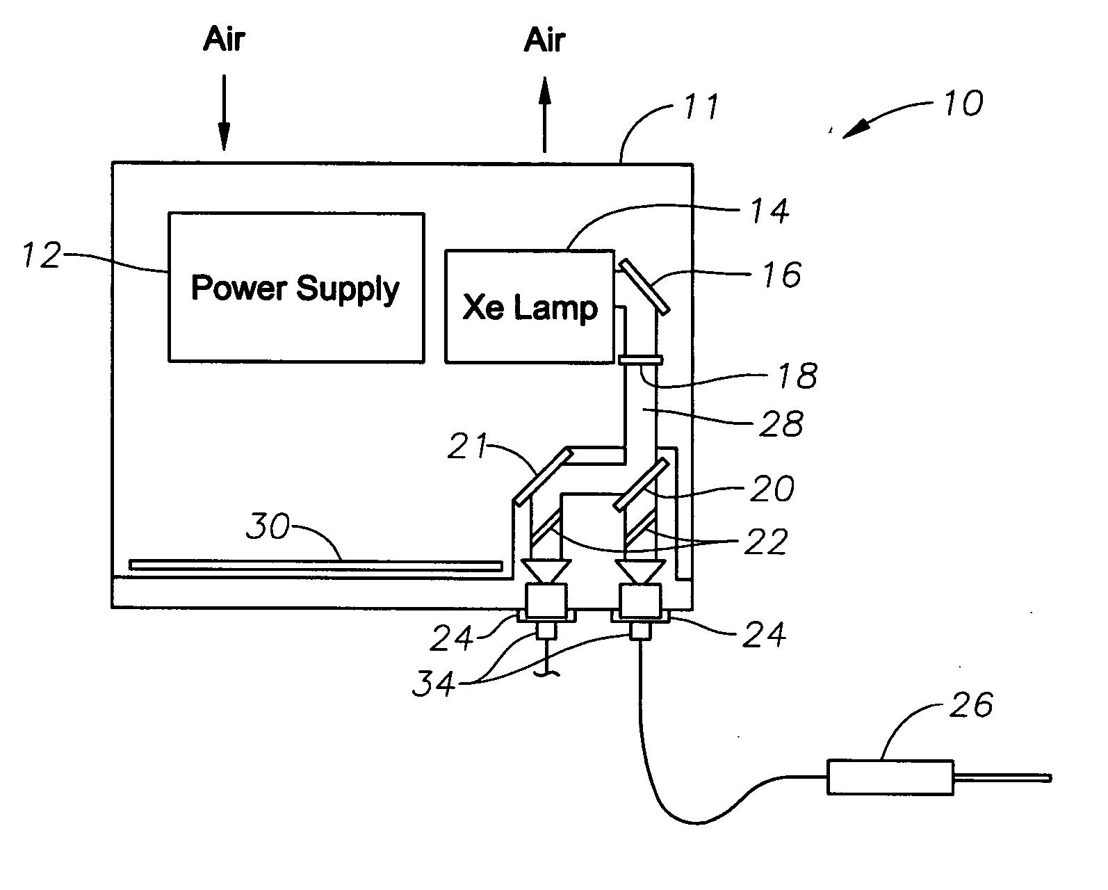
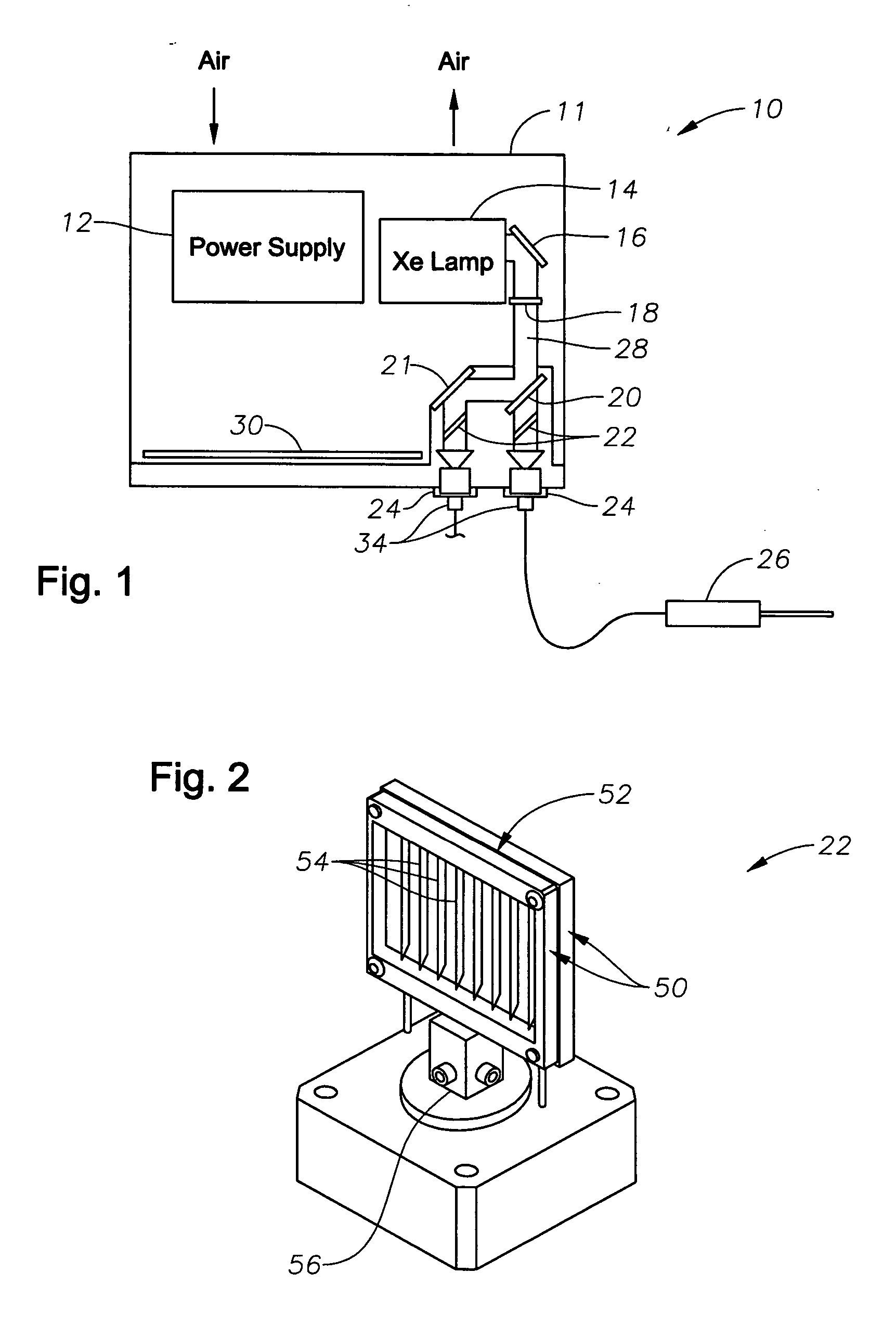
[0019] Preferred embodiments of the present invention are illustrated in the FIGURES, like numerals being used to refer to like and corresponding parts of the various drawings.

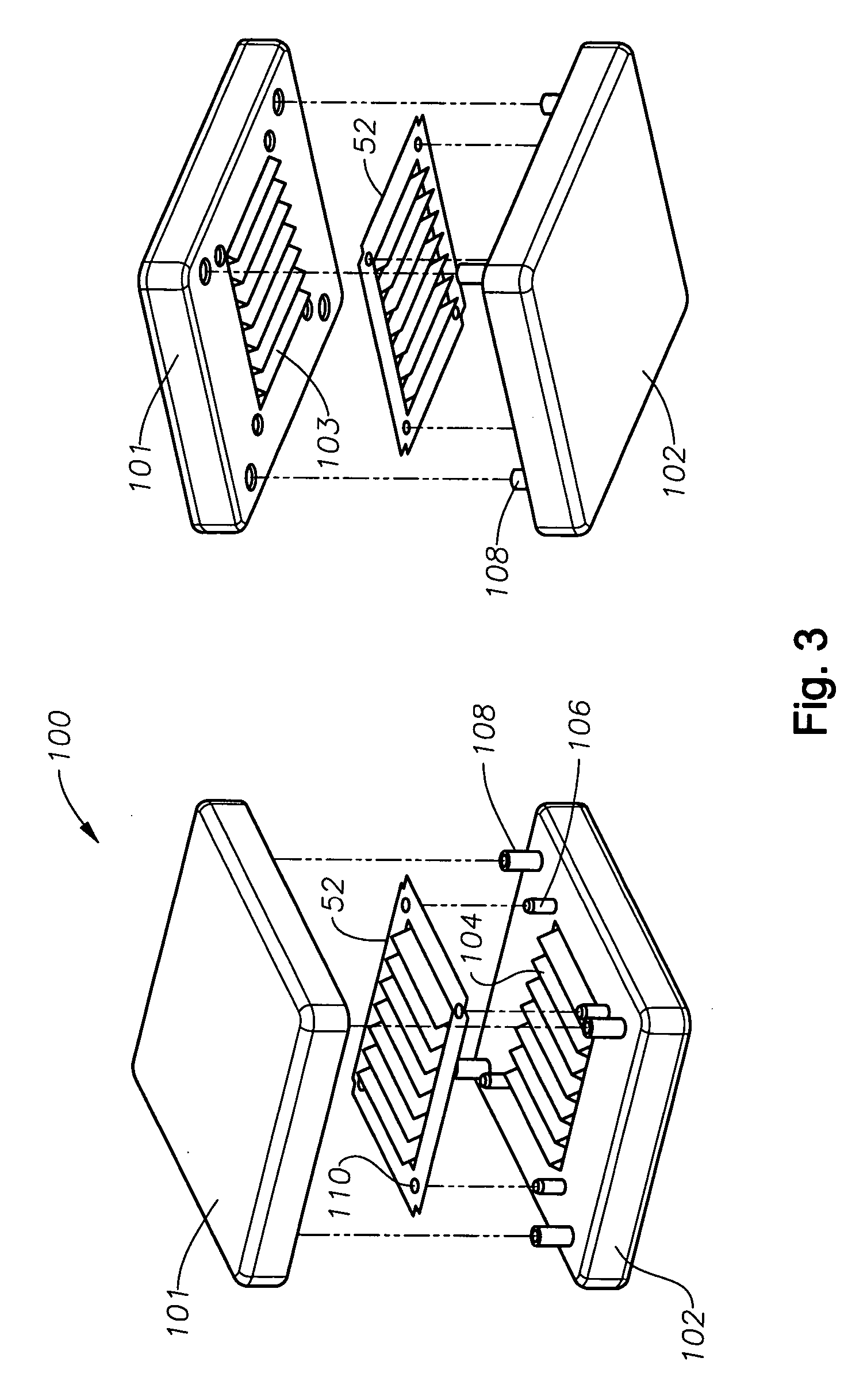
[0020] The various embodiments of the present invention provide for spatially distributed, spectrally neutral optical attenuation of an optical beam. In ophthalmic surgery there is often a need to attenuate a wide aperture optical beam (e.g., ultra-violet, Visible, Infra red, etc.) in a homogeneous manner (equal attenuation per square area) over the beam aperture. Further, there is a need to be able to vary the degree of attenuation as needed and to have the attenuation be spectrally neutral within the desired range of attenuation. The embodiments of the apparatus, method and system for spatially distributed, spectrally neutral optical attenuation of this invention can provide these functions by following simple principles analogous to those of Venetian blinds mounted on a solid frame.

[0021] Rotating a frame...


PUM


Abstract

A system, apparatus and method for spatially distributed, spectrally neutral optical attenuation are disclosed. One embodiment of the apparatus comprises: an attenuator fin plate; a set of attenuator fins, wherein each of the fins is operably coupled to the fin plate at a preset fin angle to the fin plate normal such that the attenuator fins maintain their position relative to the fin plate as the fin plate moves; and a means for rotating the fin plate a set angular distance around an axis of rotation, wherein the axis of rotation is at a preset fin plate angle to a light beam direction of travel and wherein the attenuator fins block varying amounts of the light beam as the fin plate is rotated through the set angular distance. The attenuator fin plate and attenuator fins can be a single, integral component, wherein the attenuator fin plate is etched and stamped to form the attenuator fins, or separately formed components that are attached, for example, to a separate frame. The means for rotating the fin plate would then comprise means to rotate the attenuator frame. Means for rotating the attenuator fin plate or frame can include a stepper motor, for discrete step positions, or a continuously variable motor for infinitely variable positioning. The means for rotating the attenuator fin plate or frame can be electronically controlled, for example, by a microprocessor on a printed circuit board or other such controller as known to those having skill in the art. The preset fin angle can be 31 degrees, and the preset fin plate angle can be 90 degrees. Each of the attenuator fins can be operably coupled to the fin plate at the same preset fin angle and the fin plate and/or frame centered on the axis of rotation. Each fin's major axis can be parallel to every other fin's major axis, and the axis of rotation can be parallel to each fin's major axis. The set of attenuator fins can comprise eight attenuator fins and the attenuator fins can be spaced equally apart from one another. The attenuator fin plate and set of attenuator fins can be sized so as to interfere with the entire light beam cross-section/aperture at a position along the set angular distance corresponding to zero percent of the optical beam passing through the attenuator fins. The embodiments of the attenuator of this invention can be configured for use within an ophthalmic high brightness illumination system.

Description

[0001] This application claims priority from U.S. Patent Application Ser. No. 60 / 601364 filed Aug. 13, 2004.TECHNICAL FIELD OF THE INVENTION [0002] The present invention relates generally to surgical instrumentation. In particular, the present invention relates to surgical instruments for illuminating a surgical area during eye surgery. Even more particularly, the present invention relates to spatially distributed, spectrally neutral optical attenuators for such surgical instruments that can homogeneously attenuate an optical beam. BACKGROUND OF THE INVENTION [0003] Many ophthalmic surgical procedures performed on a patient's eye require illuminating a portion of the eye so that a surgeon can properly observe the surgical site. In ophthalmic surgery, various different types of instruments are known and available for use by a surgeon to illuminate the interior of the eye. The handheld (probe) portion of a typical ophthalmic illuminator comprises a handle having a projecting tip and a...

Claims


Application Information

Patent Timeline
Patent Type & Authority Applications(United States)
IPC IPC(8): G01B9/02
CPCA61B19/52G02B26/02A61B19/5202A61B90/36A61B90/30
Inventor ARTSYUKHOVICH, ALEXANDER N.ROWE, T. SCOTTLASSALAS, BRUNO X.DARNELL, LAWRENCEKOZLOWSKI, W. JAKE JR.
Owner ALCON INC
Why Eureka
Try Eureka