System and method for generating a flickering flame effect

a technology of flickering flame and system, which is applied in the direction of capillary burners, combustion types, lighting and heating apparatuses, etc., can solve the problems of not providing a realistic flickering flame effect, unsafe, or bulky foregoing devices, and achieves the effect of safe and easy manufacturing

Active Publication Date: 2006-02-16
L&L CANDLE CO LLC
View PDF29 Cites 165 Cited by
  • Summary
  • Abstract
  • Description
  • Claims
  • Application Information

AI Technical Summary

Benefits of technology

[0008] The foregoing devices are either bulky, unsafe or do not provide a realistic flickering flame effect. Thus, the system discussed below includes

Problems solved by technology

The foregoing devices are either bulky, unsafe or

Method used


Image

  • System and method for generating a flickering flame effect
  • System and method for generating a flickering flame effect
  • System and method for generating a flickering flame effect

Examples


Embodiment Construction

[0033] Although specific embodiments of the present disclosure will now be described with reference to the drawings, it should be understood that such embodiments are by the way of example only and merely illustrative of but a small number of the many possible specific embodiments which can represent applications of the principles of the present disclosure. Various changes and modifications obvious to one skilled in the art to which the present disclosure pertains are deemed to be within the spirit, scope and contemplation of the present disclosure as further defined in the appended claims.

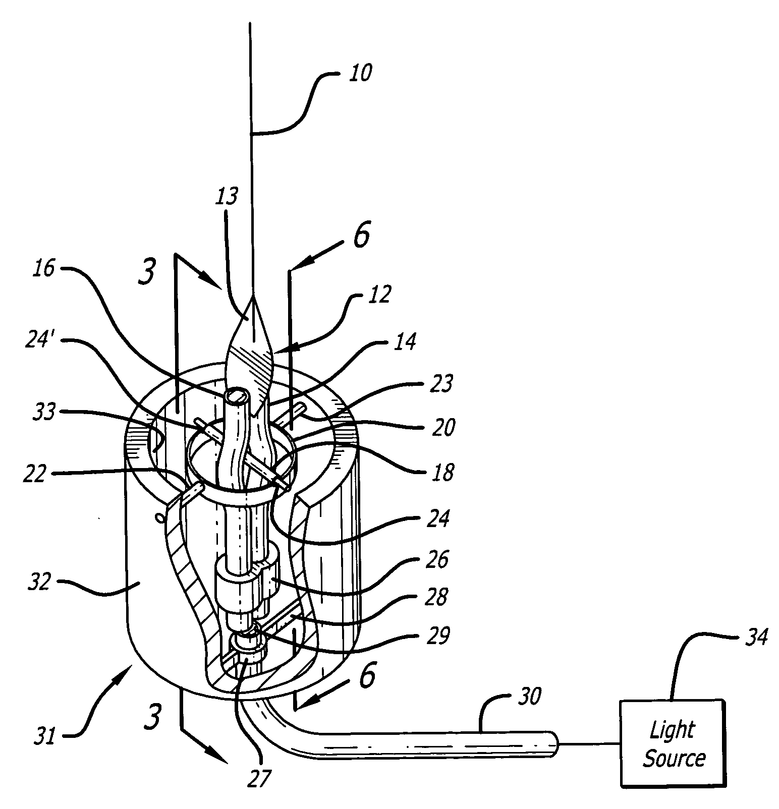
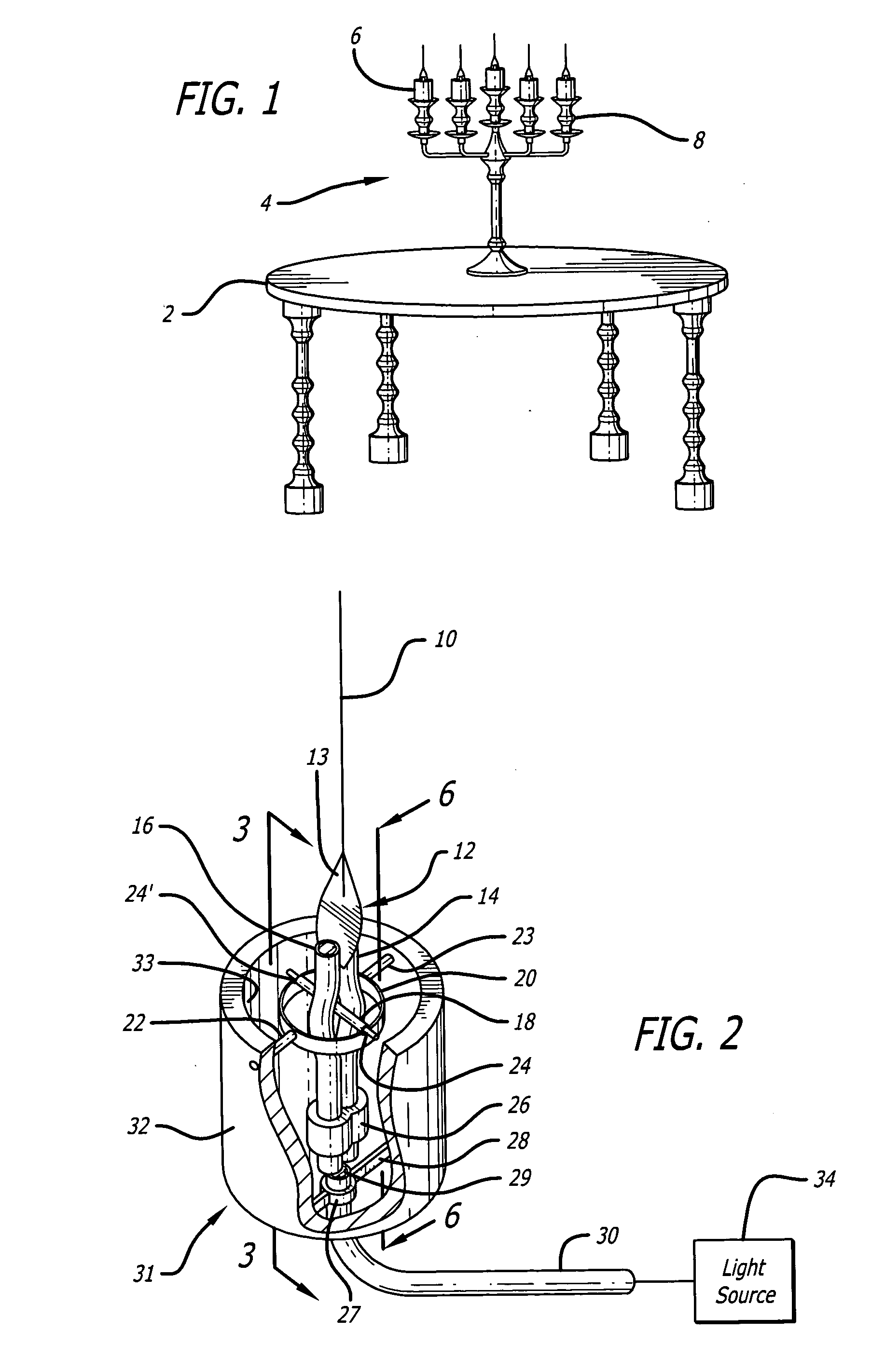
[0034]FIG. 1 is an exemplary depiction of a candelabrum 4 holding several artificial flickering flame devices 6 mounted on a table 2. The devices 6 are shown as candle shaped and are positioned on individual supports 8 of the candelabrum 4. Of course, the devices 6 may be other shapes, and need not resemble cylindrical candles per se, but could be any whimsical or geometric shape, just as candles...


PUM


Abstract

A system for creating a flickering effect comprising a simulated candle housing, a light communicating channel on the housing, a source of ultraviolet light disposed in the channel, and a simulated flame having ultraviolet material thereon movable back and forth from its vertical axis mounted in the housing, the light focused on the simulated flame simulating a flickering flame.

Description

CROSS-REFERENCE TO RELATED APPLICATIONS [0001] This application is a continuation-in-part of application Ser. No. 10 / 915,794 filed Aug. 10, 2004.BACKGROUND [0002] The present disclosure relates generally to the creation of artificial light effects for entertainment and novelty applications. DESCRIPTION OF THE BACKGROUND ART [0003] The generation of a flickering flame effect is important in entertainment applications, since it provides a mechanism for simulating the flicker of a candle without actually using a candle. This is important since it provides numerous safety benefits as well as an ability to keep the artificial flame “burning” in the presence of significant air pressure variations. [0004] One type of device that generates an artificial flame is commonly known as a “wiggle wire ball.” Specifically, this device is a relatively large ball that has a flat filament, wherein the current in the filament takes a random path which alters from time to time, thereby simulating a flic...

Claims


Application Information

Patent Timeline
IPC IPC(8): F21V15/00
CPCB44C5/06B44F1/00F21S6/00F21S6/001Y10S362/81F21S10/04F21V9/16F21Y2101/02G02B6/0008F21S10/005F21Y2115/10F21V13/14
Inventor SCHNUCKLE, GARYIRMLER, HOLGERAYALA, ALFREDOROBERTSON, JAMIETYE, BRYAN S.
Owner L&L CANDLE CO LLC
Why Eureka
Try Eureka