Unlock instant, AI-driven research and patent intelligence for your innovation.

Modulation device and transmitter comprising such a device

a technology of modulation device and transmitter, which is applied in the direction of modulation, modulated carrier system, transmission, etc., to achieve the effect of reducing the noise transmitted at the outpu

Active Publication Date: 2006-02-16
STMICROELECTRONICS SRL
View PDF1 Cites 6 Cited by
  • Summary
  • Abstract
  • Description
  • Claims
  • Application Information

AI Technical Summary

Benefits of technology

[0019] To address the above-discussed deficiencies of the prior art, a subject of the present invention is therefore a signal modulation device for which the noise transmitted at its output is reduced.
[0032] Thus, in a modulation device according to the invention, the amplitude-modulation signal is firstly converted into a pulse signal then mixed with the high-frequency signal. Two carrier signals coming from this combination are then respectively combined with each of the phase-modulation signals by means of an I / Q phase modulator. Thanks to this sequence, the noise generated by the delta-sigma modulator comprised in the signal produced by the phase modulator is reduced.
[0033] One advantage of a modulation device according to the invention results from the fact that the input channel of the amplitude-modulation signal is connected to the multiplier upstream of the respective connections of the input channels of the phase-modulation signals to the phase modulator. Thanks to this configuration, the amplitude-modulation signal and each of the phase-modulation signals exhibit reduced phase shifts. The synchronization of the modulation signals delivered by the input channels therefore only requires the implementation of small delay values.
[0034] Another advantage of a modulation device according to the invention results from the operation of the phase modulator. Indeed, the output of the phase modulator exhibits a switching rate corresponding to the operation of the delta-sigma modulator. This rate is lower than the rate of variation of the carrier signals. The result of this is a reduction in the power consumption of the phase modulator with respect to the case where the phase modulator is connected directly to the output of the phase shifter. Furthermore, the contribution of the phase modulator itself to the output signal noise of the modulation device is also reduced.

Problems solved by technology

One drawback of a transmitter of the preceding type comes from the proximity between the delta-sigma module 8 and the amplifier 101.

Method used


Image

  • Modulation device and transmitter comprising such a device
  • Modulation device and transmitter comprising such a device
  • Modulation device and transmitter comprising such a device

Examples


Embodiment Construction

[0042]FIGS. 1 and 2, discussed below, and the various embodiments used to describe the principles of the present invention in this patent document are by way of illustration only and should not be construed in any way to limit the scope of the invention. Those skilled in the art will understand that the principles of the present invention may be implemented in any suitably arranged modulated signal generation device and any transmitter comprising such a device.

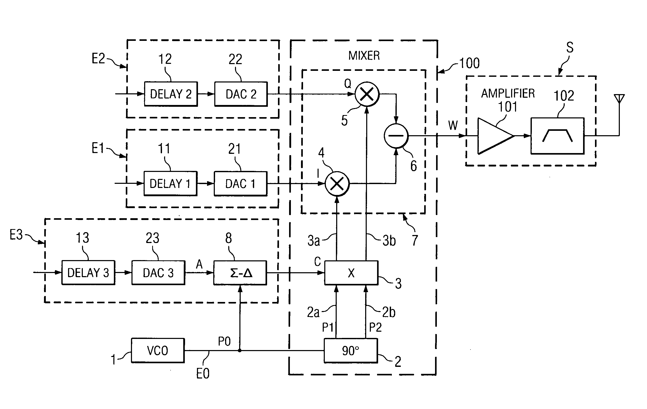
[0043] A transmitter such as will now be described in detail again comprises a signal modulation device as input stage and a power stage S disposed at the output. The modulation device comprises input channels E0, E1, E2 and E3 that are identical to those described with reference to FIG. 1. The power stage S is also identical to that described above.

[0044] In particular, the input channels for the phase-modulation signals E1 and E2 each comprise a digital-to-analogue converter, 21, 22 respectively, connected to an output of ...


PUM


Abstract

A signal modulation device comprises a delta-sigma modulator disposed for transforming an amplitude-modulation signal in baseband into a pulse signal. It also comprises a phase modulator receiving, at its input, analogue phase-modulation signals in baseband. The pulse signal is mixed with carrier signals upstream of the phase modulator. The modulation device is designed to form an input stage of a transmitter.

Description

TECHNICAL FIELD OF THE INVENTION [0001] The present invention relates to a modulated signal generation device adapted to transmit a signal containing information encoded in baseband using both phase modulation and amplitude modulation. It also relates to a transmitter comprising such a device. BACKGROUND OF THE INVENTION [0002] The article “A Class-S RF Amplifier Architecture with Envelope Delta-Sigma Modulation” by Yuanxun Wang (IEEE 2002) describes a modulation device in which all of the information encoded in baseband using phase or amplitude modulation is transformed by a delta-sigma modulator before being transposed onto a carrier. [0003] In the article “Linear High-Efficiency Microwave Power Amplifiers Using Bandpass Delta-Sigma Modulators” by Arun Jayaraman et al. (IEEE Microwave and Guided Wave Letters, Vol. 8, No. 3, March 1998), the base-band signals are converted into pulses using a bandpass delta-sigma modulator. [0004] The document U.S. Pat. No. 5,838,210 describes a ge...

Claims


Application Information

Patent Timeline
Patent Type & Authority Applications(United States)
IPC IPC(8): H04L27/20H03C5/00H03M3/02H04L27/36
CPCH04L27/206
Inventor BELOT, DIDIERGOASCOZ, VINCENT LEPACHE, DENISBERLAND, CORINNEBERCHER, JEAN-FRANCOISHIBON, ISABELLEVILLEGAS, MARTINE
Owner STMICROELECTRONICS SRL