Hole-assisted holey fiber and low bending loss multimode holey fiber

a multi-mode, hole-assisted technology, applied in the direction of instruments, optical waveguide light guides, optical light guides, etc., can solve the problems of increasing production costs, unable to completely eliminate the tradeoff between a lower bending loss and a longer cut-off wavelength, and unable to achieve both a short cut-off wavelength c/sub>and a low bending loss l/sub>b /sub>. , to achieve the effect o

Active Publication Date: 2006-02-16
THE FUJIKURA CABLE WORKS LTD
View PDF4 Cites 51 Cited by
  • Summary
  • Abstract
  • Description
  • Claims
  • Application Information

AI Technical Summary

Benefits of technology

[0010] It is an aspect of the present invention to provide a high-performance HAHF that realizes both a low bending loss LB and shorter cut-off wavelength λC...

Problems solved by technology

However, even through conventional holey fibers can achieve low bending loss, they cannot completely eliminate the tradeoff of a lower bending loss versus a longer cut-off wavelength (see T. Hasegawa, et al, “Novel hole-assisted lightguide fiber exhibiting large anomalous dispersion and low loss below 1 dB/km”, Proc.
However, in the struc...

Method used


Image

  • Hole-assisted holey fiber and low bending loss multimode holey fiber
  • Hole-assisted holey fiber and low bending loss multimode holey fiber
  • Hole-assisted holey fiber and low bending loss multimode holey fiber

Examples


example 1

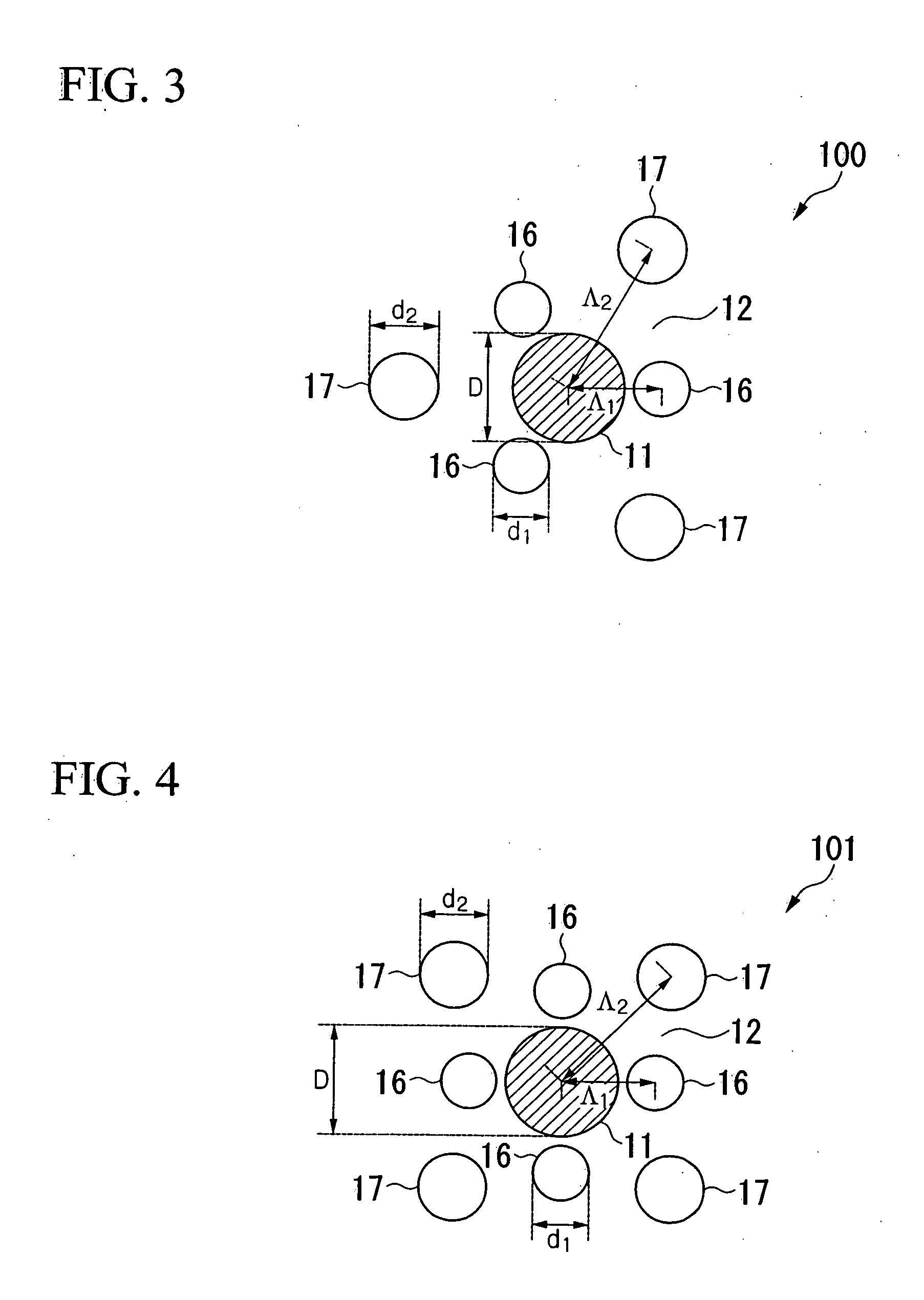
[0059] An HAHF having holes that formed two layers, i.e., the inner and outer layers, around the core region, in which the respective numbers of holes in the inner and outer layers were three, as shown in FIG. 3, was fabricated. The core region was formed from silica glass doped with GeO2, and the cladding region was formed from sure silica. The diameter D of the core region was 8.5 μm, and the relative refractive index difference Δ was 0.34%. For the inner hole layer, the hole diameter d1 was 5.1 μm, and the distance Λ1 from the center of the core region to the center of a hole was 8.5 μm. For the outer hole layer, the hole diameter d2 was 8.5 μm, and the distance Λ2 from the center of the core region to the center of the hole was 11.0 μm.

[0060] The characteristics of the fiber were measured as follows: a cut-off wavelength λC of the HAHF was about 1.24 μm and bending loss LB with a bending diameter φ of 10 mm at a wavelength of 1.55 μm was about 1.97 dB / m. Furthermore, fusion spl...

example 2

[0061] An HAHF having holes that formed two layers, i.e., the inner and outer layers, around the core region, in which the respective numbers of holes in the inner and outer layers were four, as shown in FIG. 4, was fabricated. The same materials as in the HAHF of Example 1 were used for the core region and the cladding region. The diameter D of the core region was 8.5 μm, and the relative refractive index difference Δ was 0.34%. For the inner hole layer, the hole diameter d1 was 3.6 μm, and the distance Λ1 from the center of the core region to the center of a hole was 7.5 μm. For the outer hole layer, the hole diameter d2 was 8.0 μm, and the distance Λ2 from the center of the core region to the center of the hole was 13.0 μm.

[0062] The characteristics of the fiber were measured as follows: a cut-off wavelength λC of the HAHF was about 1.28 μm and bending loss LB with a bending diameter φ of 10 mm at a wavelength of 1.55 μm was about 2.05 dB / m. Furthermore, fusion splice loss with ...

example 3

[0063] An HAHF having holes that formed two layers, i.e., the inner and outer layers, around the core region, in which the respective numbers of holes in the inner and outer layers were six, as shown in FIG. 5, was fabricated. The same materials as in the HAHF of Example 1 were used for the core region and the cladding region. The diameter D of the core region was 8.5 μm, and the relative refractive index difference Δ was 0.34%. For the inner hole layer, the hole diameter d1 was 3.3 μm, and the distance Λ1 from the center of the core region to the center of a hole was 6.8 μm. For the outer hole layer, the hole diameter d2 was 6.8 μm, and the distance Λ2 from the center of the core region to the center of the hole was 14.0 μm.

[0064] The characteristics of the fiber were measured as follows: a cut-off wavelength λC of the HAHF was about 1.29 μm and bending loss LB with a bending diameter φ of 10 mm at a wavelength of 1.55 μm was about 1.70 dB / m. Furthermore, fusion splice loss with a...


PUM


Abstract

A hole-assisted holey fiber is provided. The holey fiber includes a core region; a cladding region around the core region, and a plurality of holes in the cladding region around the core region. The core region has a higher refractive index than that of the cladding region. The holes form an inner hole layer and an outer hole layer, and the inner hole layer has the same number of holes as the number of the holes in the outer hole layer. The outer layer holes are provided in locations in which inner holes are absent when viewed from the center of the core region, and holes defining the same layer have the same diameter. A distance Λ1 from a center of the core region to a center of an inner hole and a distance Λ2 from the center of the core region to a center of an outer hole satisfy the relationship Λ12, and a diameter d1 of an inner hole and a diameter d2 of an outer hole satisfy the relationship d1≦d2.

Description

CROSS-REFERENCE TO RELATED APPLICATIONS [0001] Priority is claimed from Japanese Patent Application No. 2004-205819, filed Jul. 13, 2004, and Japanese Patent Application No. 2004-279453, filed Sep. 27, 2004, the contents of which are incorporated herein by reference. BACKGROUND OF THE INVENTION [0002] House wiring optical fibers used for the FTTH (fiber to the home) technique desirably have excellent bending loss characteristics when flexibility of laying cables and ease of installation are taken into consideration. Although improvement in bending loss characteristics can be achieved by increasing a relative refractive index difference between the core and cladding, an increased relative refractive index difference increases containment of higher-order modes, thereby making cut-off wavelengths in higher-order modes longer. [0003] A hole-assisted holey fiber (HAHF) has been proposed as a significantly low-loss fiber compared to typical single-mode fibers (hereinafter abbreviated as “...

Claims


Application Information

Patent Timeline
IPC IPC(8): G02B6/032
CPCG02B6/02333G02B6/14G02B6/02361G02B6/02357
Inventor GUAN, NINGTAKENAGA, KATSUHIROIZOE, KATSUAKIAIKAWA, KAZUHIKOHIMENO, KUNIHARU
Owner THE FUJIKURA CABLE WORKS LTD
Why Eureka
Try Eureka