Power control in a wireless communication system

a wireless communication system and power control technology, applied in the direction of power management, multiplex communication, wireless communication, etc., can solve the problems of interference with the reception of other signals sharing the radio link, unsatisfactory effect of delivered services, and voice calls being broken

Active Publication Date: 2006-02-16
INTELLECTUAL VENTURES II
View PDF33 Cites 135 Cited by
  • Summary
  • Abstract
  • Description
  • Claims
  • Application Information

AI Technical Summary

Benefits of technology

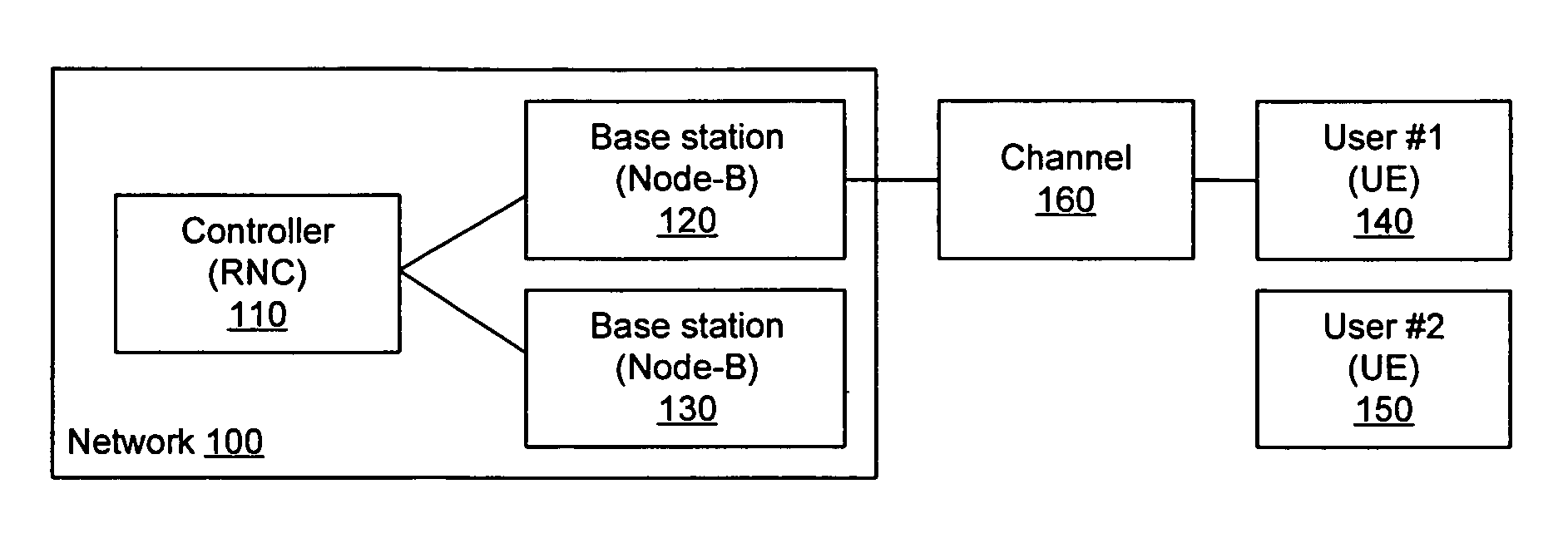
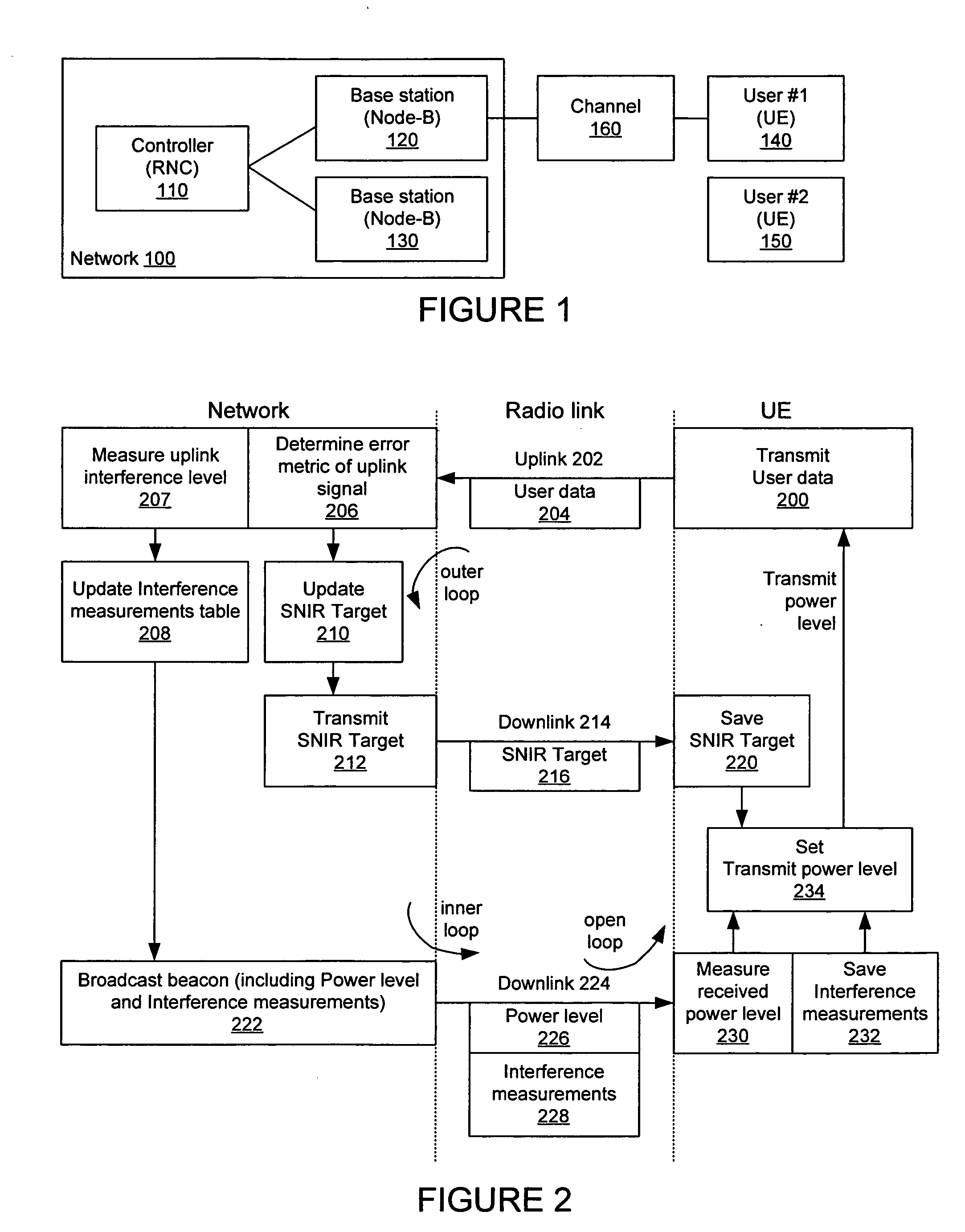
[0014] Some embodiments provide a method of power control in a radio communications system, the method comprising: determining a path loss of a radio channel between a base station and a remote transceiver; receiving a transmit power control (TPC) command transmitted to the remote transceiver from the base station; and calculating a transmit power level for the remote transceiver based on the path loss and the TPC command.

Problems solved by technology

Unfortunately, signals transmitted with excessive power may interfere with the reception of other signals sharing the radio link.
If a received signal includes a rate of errors far above a target error rate, the received signal may result in an undesirable effect on a delivered service.
For example, excessive errors may lead to broken voice during voice calls, low throughput over data links, and glitches in displayed video signals.
On the other hand, if the received signal includes a rate of errors well below the target error rate, the mobile radio system is not efficiently using its radio resources.
A very low error rate may mean that a signal is transmitted with an excessive level of power and that user could be provided a higher data rate.
The error rate is related to a received signal to noise-plus-interference ratio (SNIR); a higher SNIR generally results in a lower error rate; and conversely, a lower SNIR generally results in a higher error rate.
Unfortunately, this open loop method is relatively slow at compensating for changes due to interfering signals from other transmitters.
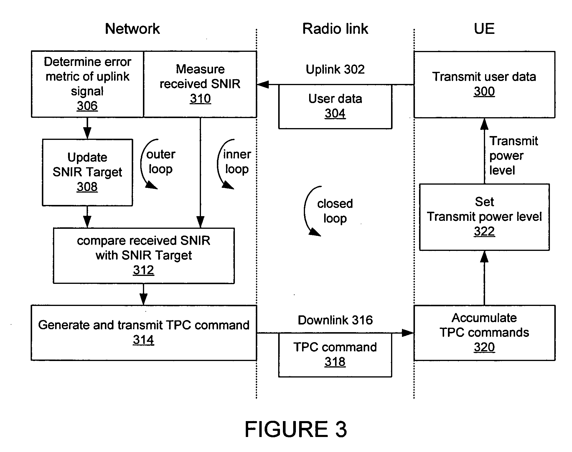
Unfortunately, such closed loop methods demand a very high command update rate to adequately compensate for fast channel fading because of the single-dB-step commands used.
At slower update rates, fast channel fading is not tracked adequately since a large number of iterations and long delays are needed to compensate for a change in power that is substantially larger than the dB-step value.

Method used


Image

  • Power control in a wireless communication system
  • Power control in a wireless communication system
  • Power control in a wireless communication system

Examples


Embodiment Construction

[0025] In the following description, reference is made to the accompanying drawings which illustrate several embodiments of the present invention. It is understood that other embodiments may be utilized and mechanical, compositional, structural, electrical and operational changes may be made without departing from the spirit and scope of the present disclosure. The following detailed description is not to be taken in a limiting sense, and the scope of the embodiments of the present invention is defined by the claims of the issued patent.

[0026] Some portions of the detailed description which follows are presented in terms of procedures, steps, logic blocks, processing, and other symbolic representations of operations on data bits that can be performed on computer memory. A procedure, computer executed step, logic block, process etc., are here conceived to be a self-consistent sequence of steps or instructions leading to a desired result. The steps are those utilizing physical manipu...


PUM


Abstract

A method, system and apparatus for setting a transmit power control level in a wireless communication system. Aspects of both open loop and closed loop transmit power control schemes are used to determine a transmit power level. A method includes measuring a power level of a received signal, receiving a transmit power control (TPC) command, and calculating a transmit power level based on the power level of the received signal and the TPC command.

Description

CROSS-REFERENCE TO RELATED APPLICATIONS [0001] Not applicable. BACKGROUND OF THE INVENTION [0002] 1. Field of the Invention [0003] This invention relates to power control in a mobile radio system or wireless communication system, and more particularly, to controlling received power levels in a code division multiple access (CDMA) radio system. [0004] 2. Description of the Prior Art [0005] Typically, radio signals transmitted with increased power result in fewer errors when received than signals transmitted with decreased power. Unfortunately, signals transmitted with excessive power may interfere with the reception of other signals sharing the radio link. Wireless communication systems employ power control schemes to maintain a target error rate of a signal received on a radio link. [0006] If a received signal includes a rate of errors far above a target error rate, the received signal may result in an undesirable effect on a delivered service. For example, excessive errors may lead...

Claims


Application Information

Patent Timeline
Patent Type & Authority Applications(United States)
IPC IPC(8): H04Q7/20H04B1/69H04B1/7097H04J13/00H04W52/06H04W52/08H04W52/10H04W52/12H04W52/22H04W52/24
CPCH04W52/06H04W52/08H04W52/10H04W52/12H04W72/0473H04W52/24H04W52/242H04W52/243H04W52/221H04W28/18H04W72/21H04W72/23H04W52/241H04W72/1268
Inventor ANDERSON, NICHOLAS WILLIAM
Owner INTELLECTUAL VENTURES II
Why Eureka
Try Eureka