Dynamic network detection system and method

Inactive Publication Date: 2006-02-16
ENTERASYS NETWORKS
View PDF101 Cites 299 Cited by
  • Summary
  • Abstract
  • Description
  • Claims
  • Application Information

AI Technical Summary

Benefits of technology

[0022] The details of one or more implementations are set forth in the accompanying drawings and the descriptio

Problems solved by technology

Unfortunately, as the access to a network increases, the likelihood of a network attack (i.e., by a hacker or a computer virus, for example) also increases.
Once initiated, a network attack may result in network harm e.g., data corruption/loss/theft, network access denial, excess/complete network bandwidth consumption, network attack propagation/dissemination, and/or unwarranted or unauthorized use.
Unfortunately, the rigidity of firewalls often limits their usefulness.
Unfortunately, as network attacks spread rapidly throughout a network, any delay in taking an enforcement action may increase the severity of the attack.
Furthermore, as the network administrator typically defines and implements the enforcement action

Method used


Image

  • Dynamic network detection system and method
  • Dynamic network detection system and method
  • Dynamic network detection system and method

Examples


Embodiment Construction

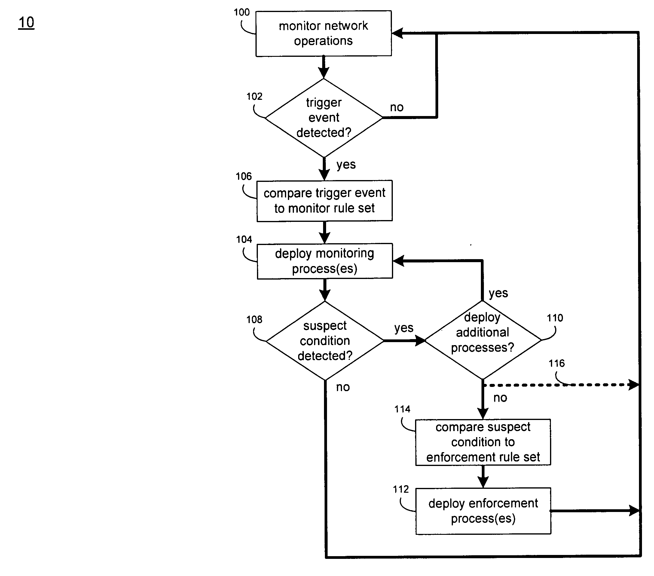
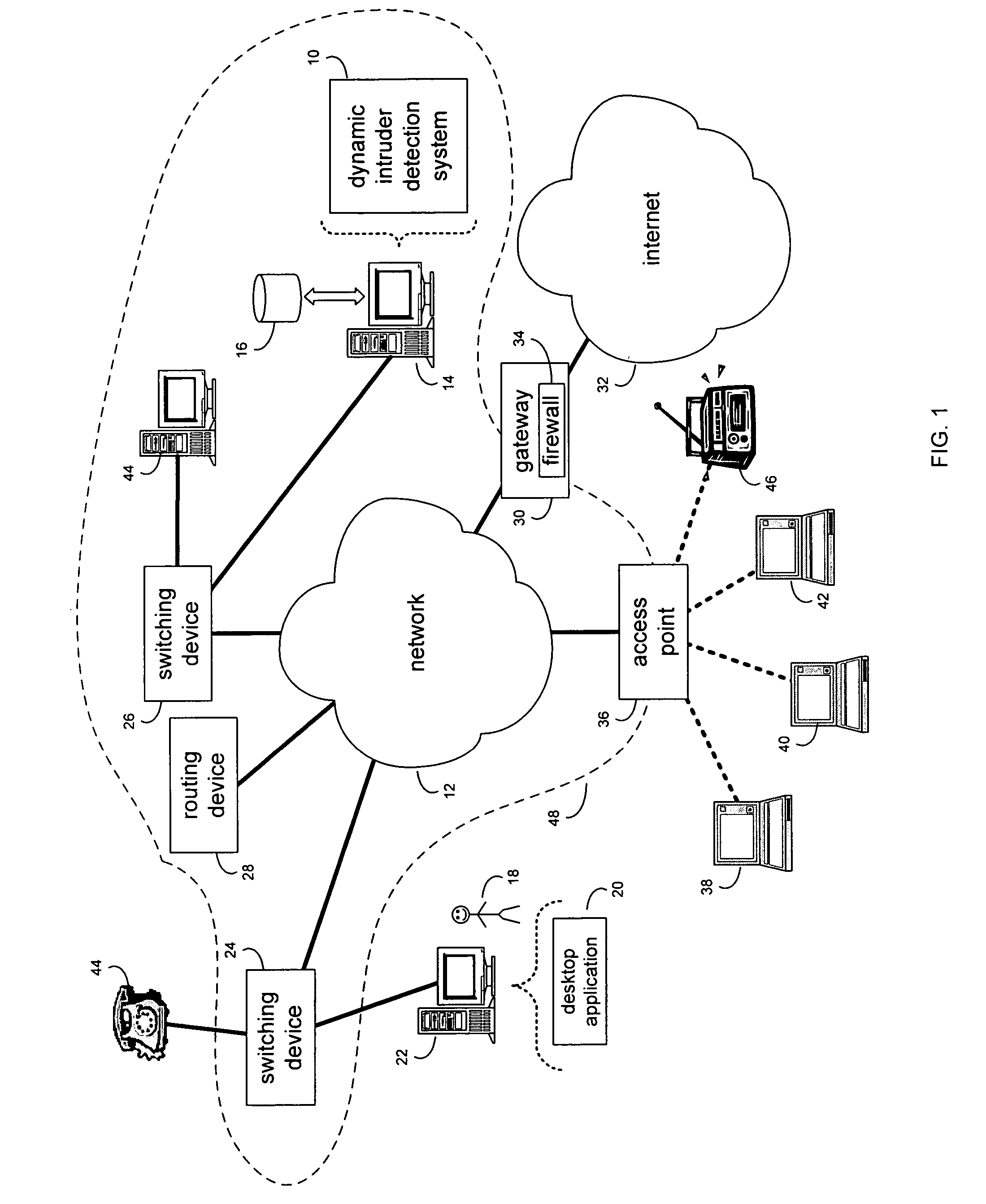
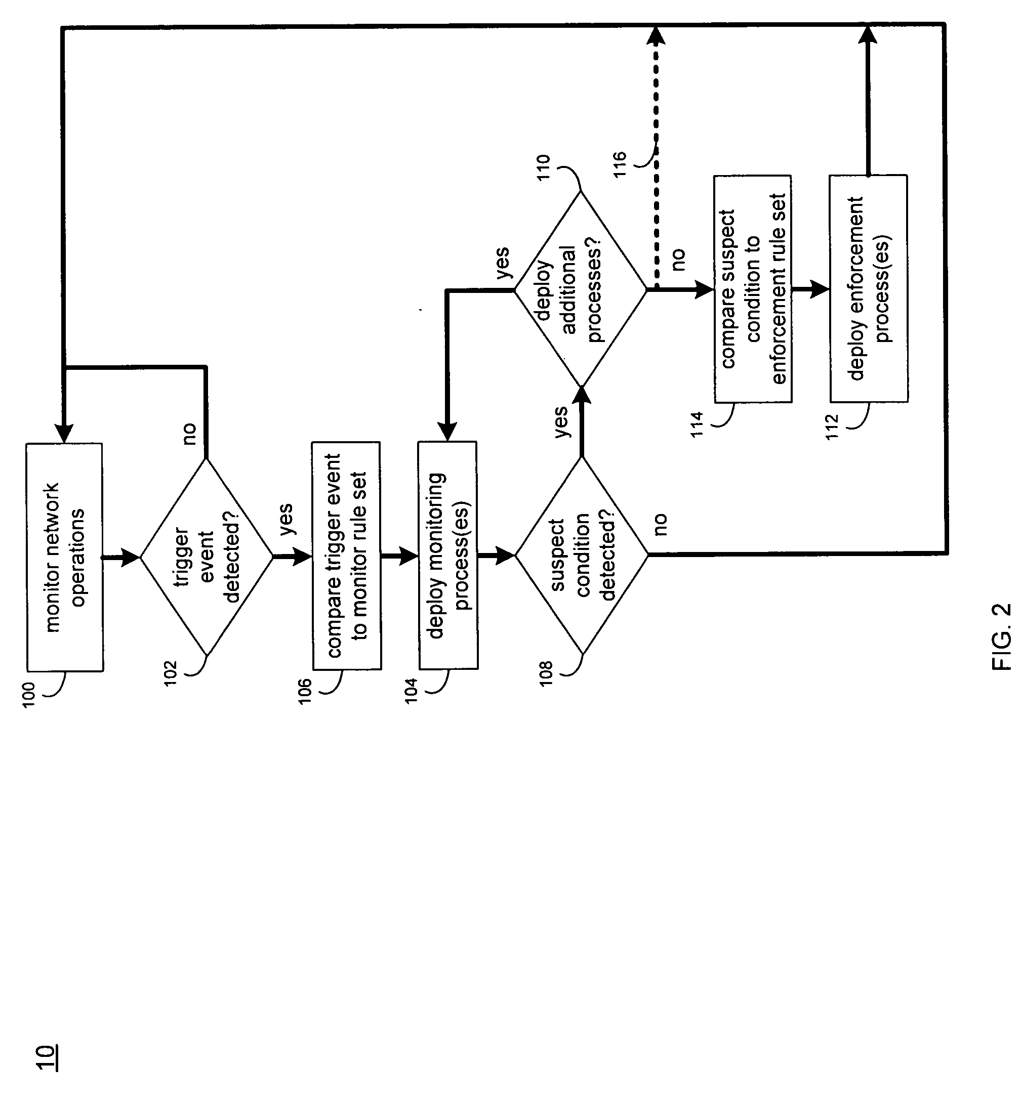
[0026] Referring to FIG. 1, there is shown a dynamic detection system 10 that monitors network traffic (e.g., data packets) on a network 12 to detect and analyze network events, and may execute one or more enforcement measures in response to the occurrence of a network event.

[0027] Dynamic detection system 10 typically resides on and is executed by one or more computing devices (e.g., server 14) connected to network 12 (e.g., a local area network, an intranet, the internet, or some other form of network). The instruction sets and subroutines of dynamic detection system 10 are typically stored on a storage device 16 connected to computing device 14.

[0028] Storage device 16 may be, for example, a hard disk drive, a tape drive, an optical drive, a RAID array, a random access memory (RAM), or a read-only memory (ROM). A network administrator 18 typically configures, accesses, and administers dynamic intruder detection system 10 through a desktop application 20 (e.g., Microsoft Interne...


PUM


Abstract

A method of dynamically launching a monitor includes monitoring network operations, occurring within a device network, to determine the occurrence of one or more trigger events. One or more event-specific monitor processes are dynamically deployed in response to the occurrence of the one or more trigger events.

Description

RELATED APPLICATIONS [0001] This application claims the priority of the following application, which is herein incorporated by reference: U.S. Provisional Application Ser. No. 60 / 552,000 entitled, “Dynamically Created Distributed Monitors in Network Systems”, filed 10 Mar. 2004. [0002] This application herein incorporates by reference the following applications: “Distributed Intrusion Response System”, U.S. patent application Ser. No. 10 / 713,560 filed Nov. 14, 2003 (attached hereto as Exhibit A) and U.S. Publication No. US20050027837A1, filed Jul. 29, 2003, entitled “System and Method for Dynamic Network Policy Management” (attached hereto as Exhibit B). Both applications are assigned to common assignee Enterasys Networks, Inc.FIELD OF THE DISCLOSURE [0003] This disclosure relates to network detection and monitoring systems and methods and, more particularly, to dynamic network detection systems and methods. BACKGROUND [0004] Networks, which may be hardwired or wireless, allow for t...

Claims


Application Information

Patent Timeline
IPC IPC(8): G06F15/173G06F12/14H04L12/24H04L12/26
CPCH04L12/2602H04L41/042H04L63/1441H04L63/1416H04L43/00
Inventor FRATTURA, DAVID E.GRAHAM, RICHARD W.
Owner ENTERASYS NETWORKS
Why Eureka
Try Eureka