High energy primary spark ignition system for a gas turbine engine

a gas turbine engine and ignition system technology, applied in the direction of machines/engines, lighting and heating apparatus, instruments, etc., can solve problems such as ice build

Active Publication Date: 2006-02-23
HAMILTON SUNDSTRAND CORP
View PDF8 Cites 13 Cited by
  • Summary
  • Abstract
  • Description
  • Claims
  • Application Information

AI Technical Summary

Benefits of technology

[0007] The present invention therefore provides an ignition system for a gas turbine engine that ensures start reliability by specifically clearing ice build-up at the ignition plugs in an inexpensive, uncomplicated and lightweight arrangement.

Problems solved by technology

In operation of gas turbine engines, specifically Auxiliary Power Units (APUs), failure to start may result due to ice build-up on the ignition plug tip.
Such occurrences may be of particular concern during high altitude operation.

Method used


Image

  • High energy primary spark ignition system for a gas turbine engine
  • High energy primary spark ignition system for a gas turbine engine
  • High energy primary spark ignition system for a gas turbine engine

Examples


Embodiment Construction

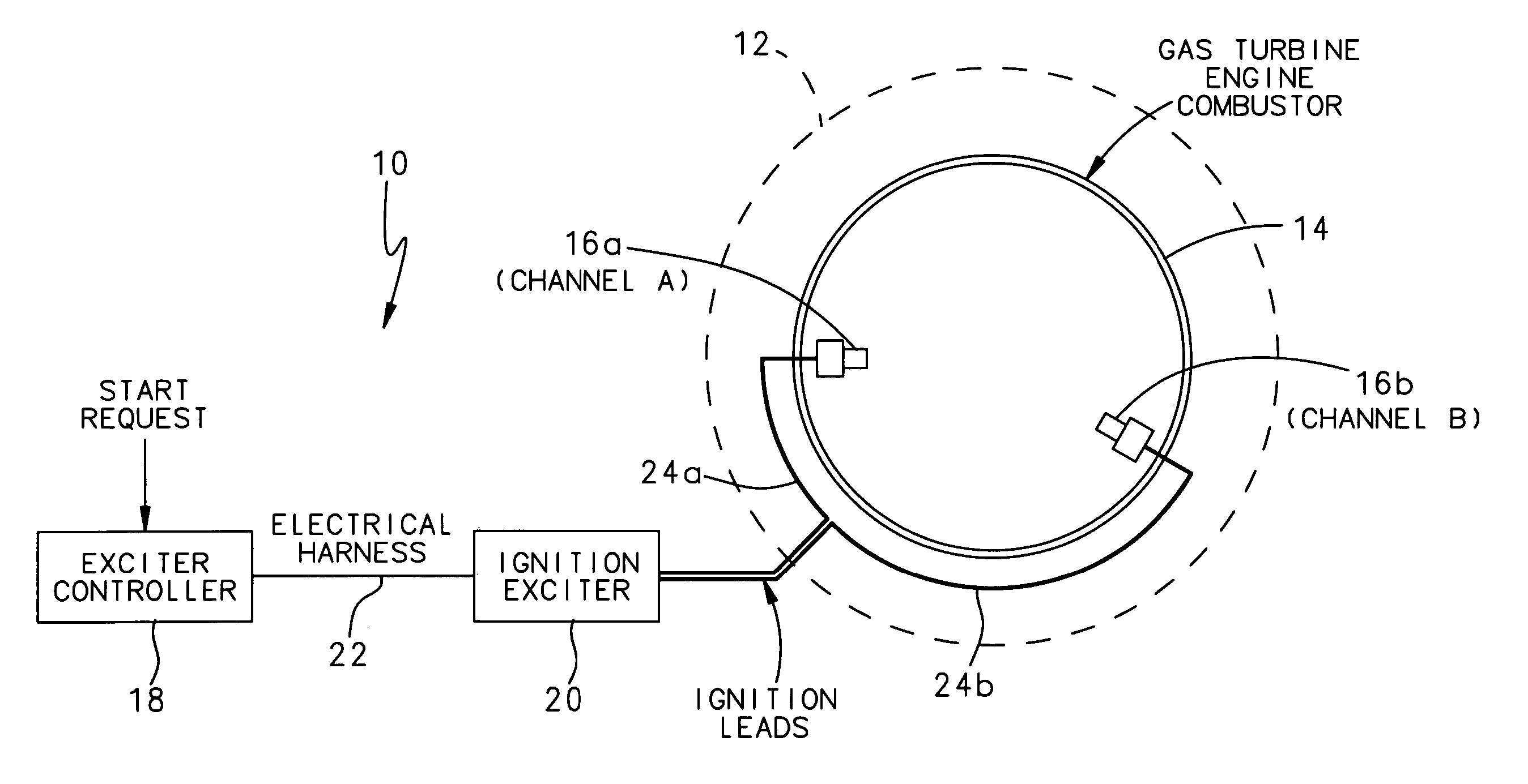
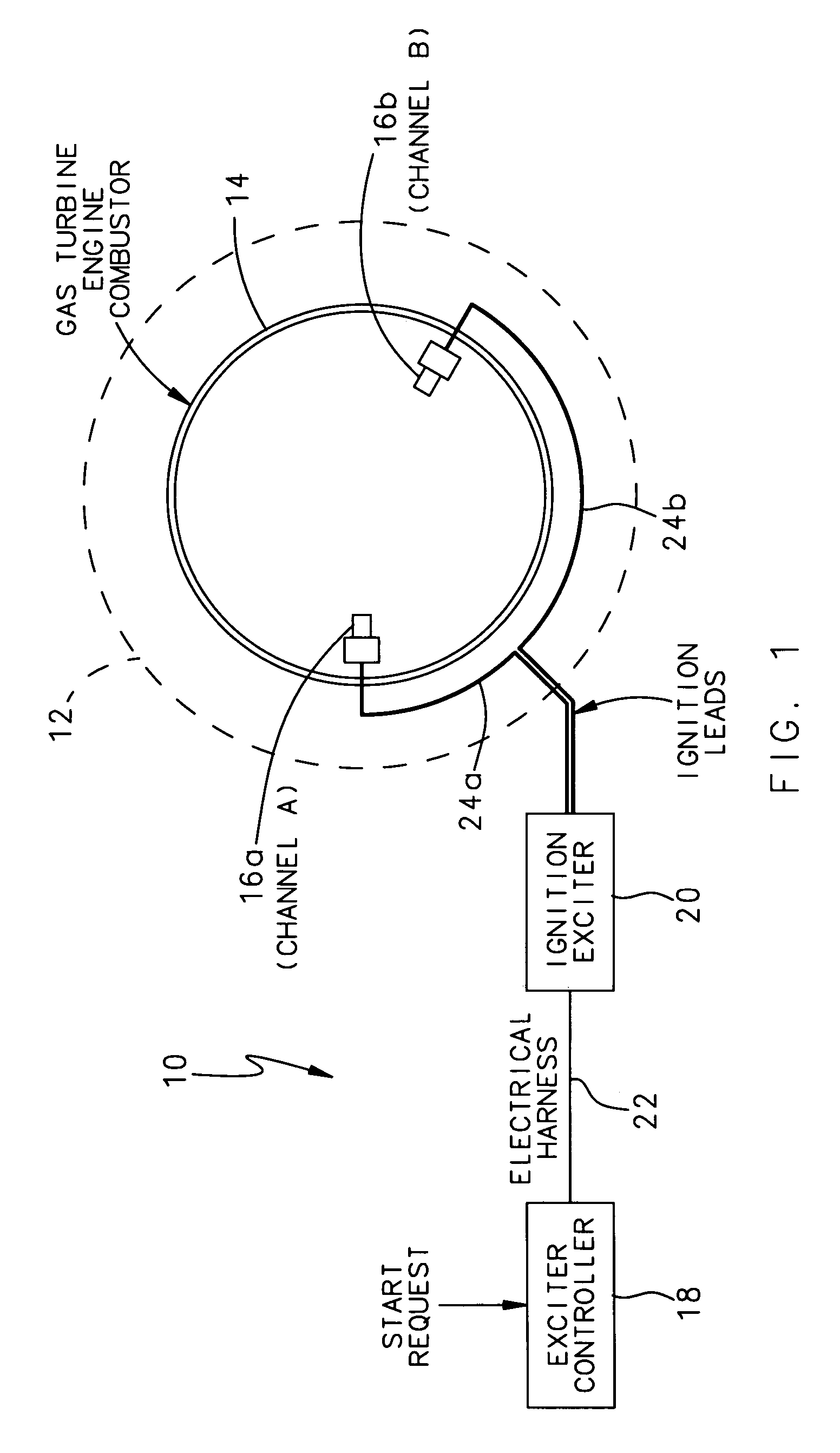
[0011]FIG. 1 illustrates a general schematic view of an ignition system 10 for a gas turbine engine 12 (illustrated schematically) such as an auxiliary power unit (APU). It should be understood that the ignition system may be used in other applications, such as in a stationary generating station or ground based unit for a vehicle or the like.

[0012] The ignition system 10 operates to ignite a fuel-air mixture in an engine combustor 14 through a first ignition plug 16a and a second ignition plug 16b. An exciter controller 18 communicates with an ignition exciter 20 through a wiring harness 22 or the like. The ignition exciter 20 drives the ignition plug 16a and the second ignition plug 16b through a first ignition lead 24a and a second ignition lead 24b, respectively in response to the exciter controller 18.

[0013] The first ignition lead 24a and the first ignition plug 16a is herein referred to as Channel A while the second ignition lead 24b and the second ignition plug 16b is herei...


PUM


Abstract

An exciter circuit for a gas turbine engine delivers a first single high-energy spark followed by subsequent sparks of relatively lower energy to ensures start reliability by specifically clearing ice build-up at the ignition plugs.

Description

BACKGROUND OF THE INVENTION [0001] The present invention relates to an ignition system for a gas turbine engine, and more particularly to an ignition system which delivers a first single high-energy spark followed by subsequent sparks of lower energy. [0002] Gas turbine engine ignition systems typically include an ignition exciter that generates the discharge energy used to fire the ignition plugs or igniters. These circuits are commonly used within the aviation industry, but are not limited to aircraft turbine engines. For example, gas turbine generators and other small turbine engines will typically utilize exciter circuits to provide spark energy to one or more igniter plugs. [0003] A start sequence for a gas turbine engine that coordinates engine speed, ignition and fuel delivery to achieve a reliable start. Conventionally, a dedicated starter motor or a starter-generator, is drivably coupled to the gas turbine engine and is operated to produce rotation thereof. As the starter a...

Claims


Application Information

Patent Timeline
Patent Type & Authority Applications(United States)
IPC IPC(8): F02C7/264
CPCF02C7/266
Inventor MEHRER, MICHAEL E.CHEN, DAIH-YEOUJAMES, JOSEPH
Owner HAMILTON SUNDSTRAND CORP
Why Eureka
Try Eureka