
Film effectiveness enhancement using tangential effusion

Inactive Publication Date: 2006-02-23
HONEYWELL INT INC
View PDF17 Cites 39 Cited by
  • Summary
  • Abstract
  • Description
  • Claims
  • Application Information

AI Technical Summary

Benefits of technology

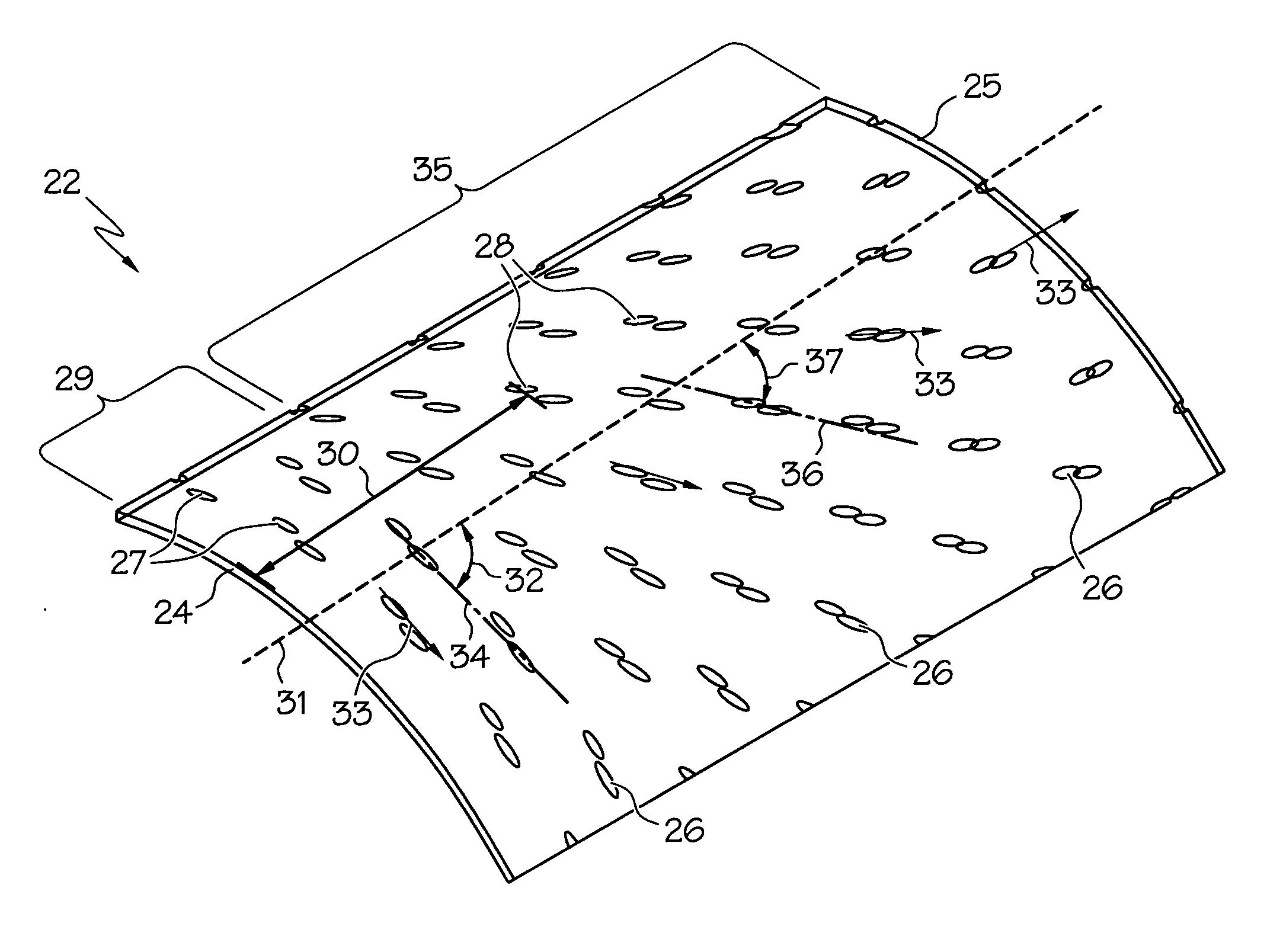
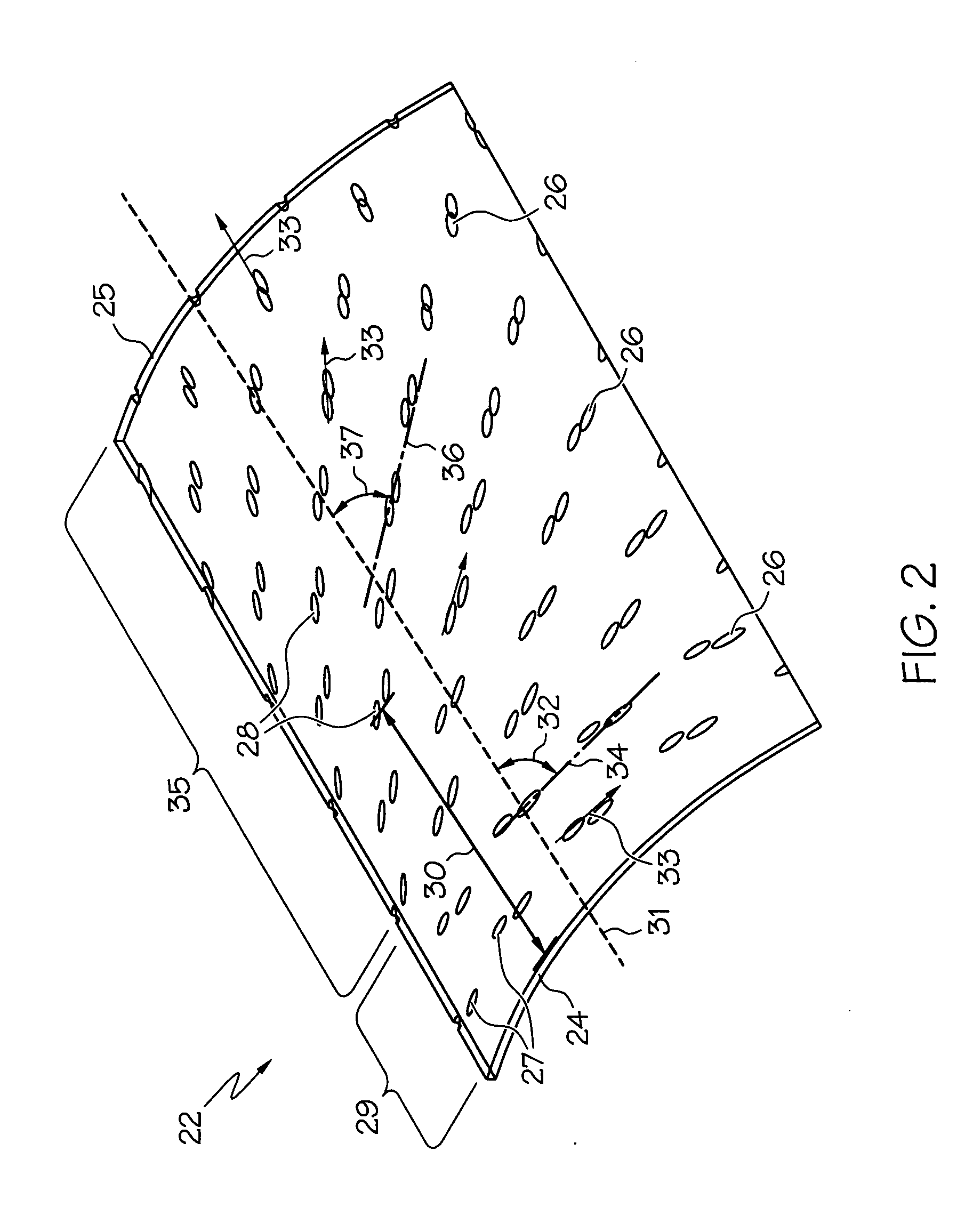
[0015] In a further aspect of the present invention, a method of enhancing the film effectiveness for an effusion cooled component comprises the step of passing a first portion of effusion flow through a plurality of initial effusion hole openings in an initial flow region of said effusion cooled component, at least one initial effusion hole opening positioned such that a longitudinal line of the effusion cooled component and a centerline of the initial effusion hole opening forms an initial hole tangential angle of between about 75° and about 90°.

Problems solved by technology

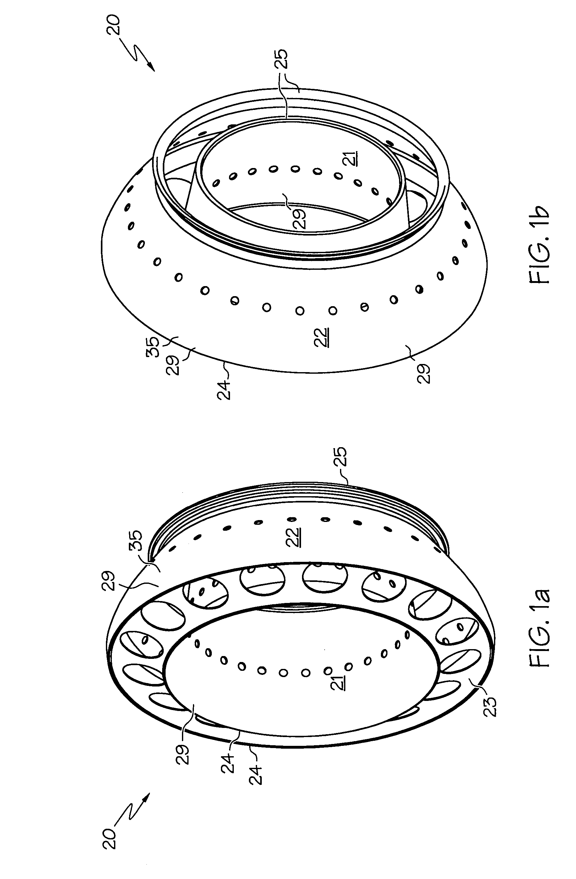
Although conventional effusion cooling may be sufficient for cooling some areas of the combustor liners, other areas of the liner are not cooled sufficiently and require additional cooling.
Although these groups of oppositely directed effusion holes may be useful in cooling hot spot areas caused by cooling film disruption, they are not useful in cooling all hot spot areas of the liner.
Although these rectangular holes may increase cooling in the cooling film shadow area caused by the dilution holes, they may not provide sufficient cooling in the initial flow region at the forward end of the liner.
The initial low film effectiveness is because conventional effusion requires 5-10 rows of effusion holes for the cooling film to develop such that the combustor wall is protected from the hot combustion gases.
The necessity of using starter skirts complicates the construction of combustors and increases their cost.
Also, in situations where the geometry does not permit the use of a starter skirt or where the effusion panel is very short, the usefulness of effusion cooling is greatly reduced.
Further, cooling augmentation is needed for applications where a starter film cooling skirt cannot be used.

Method used


Image

  • Film effectiveness enhancement using tangential effusion
  • Film effectiveness enhancement using tangential effusion
  • Film effectiveness enhancement using tangential effusion

Examples


example 1

[0040] The film effectiveness of a conventional effusion panel and an effusion panel of the present invention were compared. A plot of film effectiveness as a function of distance from start of panel is depicted in FIG. 4. The dashed curve represents the film effectiveness of a conventional axial orientation effusion panel. The solid line represents the film effectiveness of an effusion panel of the present invention. The present invention provides greater film effectiveness at the start of the effusion panel, the initial flow region. As can be appreciated by those skilled in the art, the present invention may decrease liner temperatures in the initial flow region of the panel, making starter skirts unnecessary.

example 2

[0041] The impact of tangential effusion can be seen in FIG. 5, which shows thermocouple measured liner metal temperatures for an annular combustor. The figure plots the maximum inner wall temperature as a function of the combustor discharge temperature. The axial orientation effusion panel used conventional axial effusion and generated the upper line of data. By changing to tangential effusion according to one embodiment of the present invention which transitioned to axial as discussed above, and without changing the amount of cooling flow, the lower line of data was generated which represents a reduction over 500° F. in liner temperature.

[0042] As can be appreciated by those skilled in the art, the present invention provides improved film effectiveness at the start of an effusion panel. This means that the complication and expense of starter skirts can be eliminated and / or effusion cooling can be effectively used in situations where a starter skirt is geometrically impossible.


PUM


Abstract

Film effectiveness enhancement is provided by a plurality of tangentially angled effusion holes in a combustor liner. The effusion holes positioned in the initial flow region at the start of the panel have a tangential angle between about 75° and about 90° to the combustor axis. The tangential angle of the effusion holes positioned downstream from the initial flow region is gradually reduced to a value corresponding to the bulk swirl of the combustor internal flow or to zero so that the effusion hole orientation at the end of the panel corresponds to that of convention effusion.

Description

BACKGROUND OF THE INVENTION [0001] The present invention generally relates to gas turbine engines and, more particularly, to effusion cooled components, such as combustor liners. [0002] An important component of any gas turbine engine is the combustor. Because of the high temperatures (>3500° F.) generated inside the combustor and because metals used in combustor construction are limited to 1700-1800° F., cooling must be provided for the combustor liner walls. [0003] Effusion cooling is a widely used technique for protecting gas turbine combustor liner walls from hot combustion gases. This cooling technique involves covering the combustor wall with a matrix of small holes. A supply of cooling air is passed through the holes from the cooler surface of the combustor wall to the surface exposed to higher temperatures. The cooling air actively cools the liner by convection as it passes through the hole and after the cooling air is discharged. [0004] The holes are usually 0.015 to 0.0...

Claims


Application Information

Patent Timeline
IPC IPC(8): F23R3/06
CPCF23R3/06Y02T50/675F23R2900/03041Y02T50/60
Inventor REYNOLDS, ROBERT S.DUDEBOUT, RODOLPHE
Owner HONEYWELL INT INC
Learn More