Isolation between antennas using floating parasitic elements

a technology of parasitic elements and antennas, applied in the field of antennas, to achieve the effect of improving isolation

Active Publication Date: 2006-02-23
NOKIA TECHNOLOGLES OY
View PDF12 Cites 100 Cited by
  • Summary
  • Abstract
  • Description
  • Claims
  • Application Information

AI Technical Summary

Benefits of technology

[0008] The object of the present invention is to provide a method for improving isolation between an antenna (e.g., a main antenna such as GSM antenna) and at least one further antenna (e.g., a BLUETOOTH/WLAN antenna) in an e

Problems solved by technology

However, due to compactness of the phone, it is not feasible to introduce additional grou

Method used


Image

  • Isolation between antennas using floating parasitic elements
  • Isolation between antennas using floating parasitic elements
  • Isolation between antennas using floating parasitic elements

Examples


Embodiment Construction

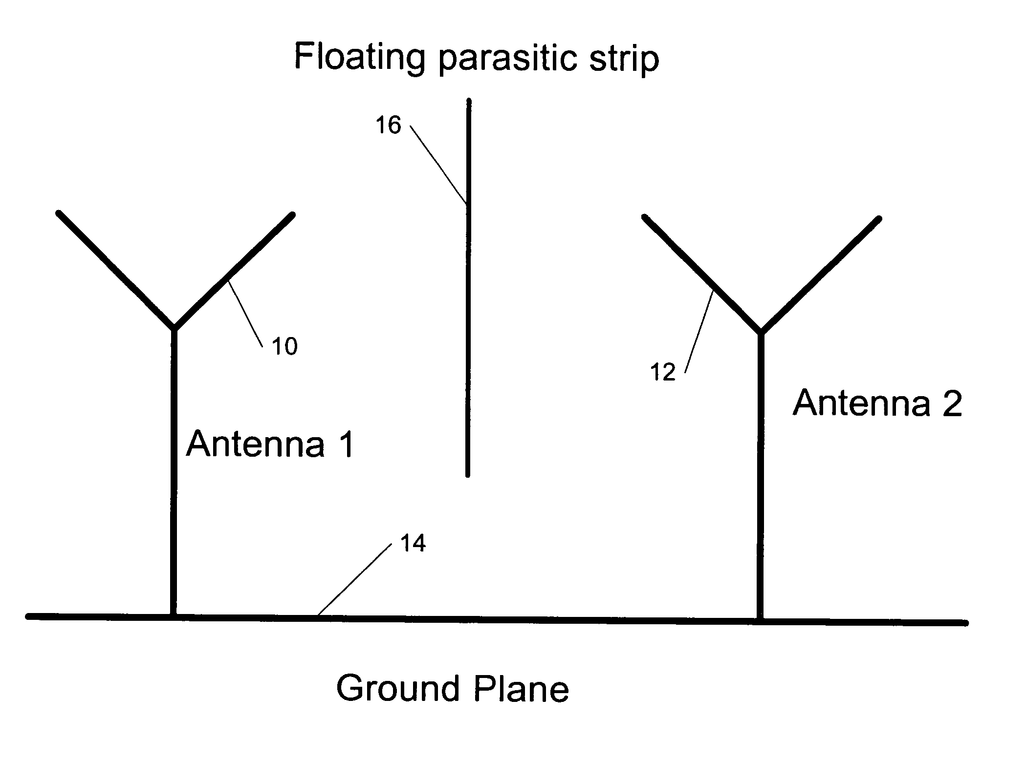
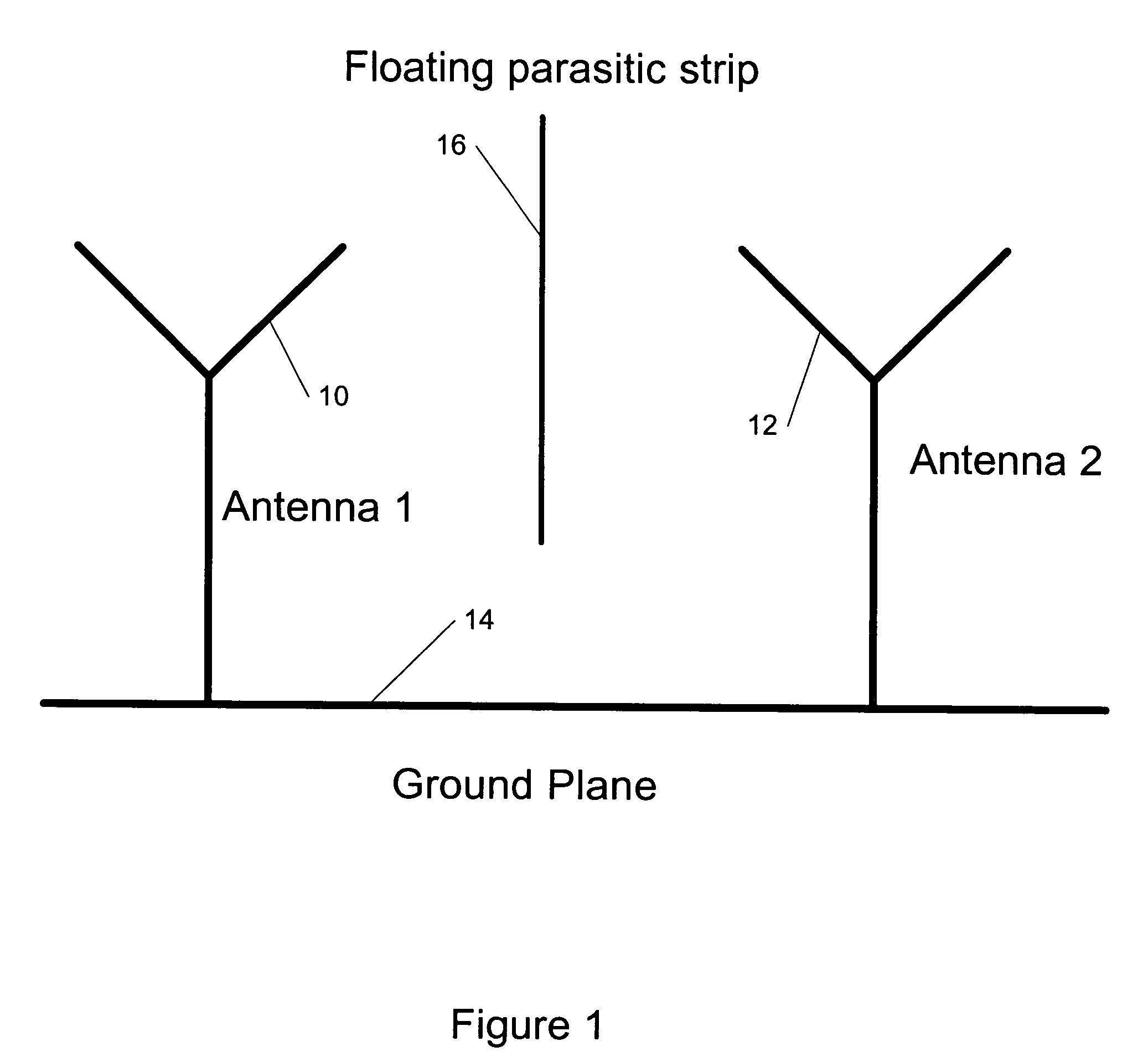
[0033] The present invention provides a new method for improving isolation between an antenna (e.g., a main antenna) and at least one further antenna (e.g., a BLUETOOTH / WLAN antenna, a diversity antenna, etc.) in an electronic communication device by a parasitic element placed physically between these two antennas for providing an isolation from electro-magnetically coupled currents between these two antennas in a ground plane, wherein the antennas are connected to the ground plane and said parasitic element is floating and electrically isolated from the ground plane.

[0034] According to the present invention, the electronic communication device can be (but is not limited to) a portable communication device, a mobile electronic device, a mobile phone, or a handset. Moreover, the antenna and the further antenna typically can have different operating frequency ranges as well as the same operating frequency (e.g., for the diversity antennas). Furthermore, in the mobile phone the main a...


PUM


Abstract

This invention describes a method for improving isolation between the main antenna (e.g., a GSM antenna) and at least one further antenna (e.g., a BLUETOOTH/WLAN antenna, a diversity antenna, etc.) in an electronic communication device by a floating parasitic element placed between these two antennas for providing an isolation from electro-magnetically coupled currents between these two antennas in a ground plane, wherein the antennas are connected to the ground plane and the parasitic element is floating and electrically isolated from the ground plane. The advantages of the present invention include but are not limited to a more compact placement of antennas and a reduced cost and better reliability compared to an approach involving grounded parasitic elements.

Description

CROSS-REFERENCE TO RELATED APPLICATION [0001] This application claims priority from U.S. Provisional Patent Application Ser. No. 60 / 603,452 filed Aug. 20, 2004.TECHNICAL FIELD [0002] This invention generally relates to antennas and more specifically to improving isolation between antennas in handsets or wireless communication devices. BACKGROUND ART [0003] Handsets and other wireless communication devices are undergoing miniaturization. As a result, there is a continuing interest in small antennas that can be internally mounted to the handsets. [0004] In addition, it is desirable for radiophones to be able to operate within multiple frequency bands in order to utilize more than one communication system. For example, the frequency bands allocated in North America are from 824 to 894 MHz for Advanced Mobile Phone Service (AMPS, or Cell band) and from 1850 to 1990 MHz for Personal Communication Services (PCS). GSM (Global System for Mobile communications) is a digital mobile telephone ...

Claims


Application Information

Patent Timeline
IPC IPC(8): H01Q21/00
CPCH01Q1/521H01Q1/243
Inventor HUI, PINGVAN-WONTERGHEM, JARI
Owner NOKIA TECHNOLOGLES OY
Why Eureka
Try Eureka