
Noise reduction apparatus, method and program

a technology of noise reduction and noise reduction apparatus, applied in the field of noise reduction apparatus and method and to noise reduction program, can solve the problems of affecting noise, unable to achieve effective noise reduction, and therefore, achieve the effect of reducing noise effectively

Inactive Publication Date: 2006-02-23
FUJIFILM CORP
View PDF4 Cites 33 Cited by
  • Summary
  • Abstract
  • Description
  • Claims
  • Application Information

AI Technical Summary

Benefits of technology

[0006] Accordingly, an object of the present invention is to reduce noise effectively.
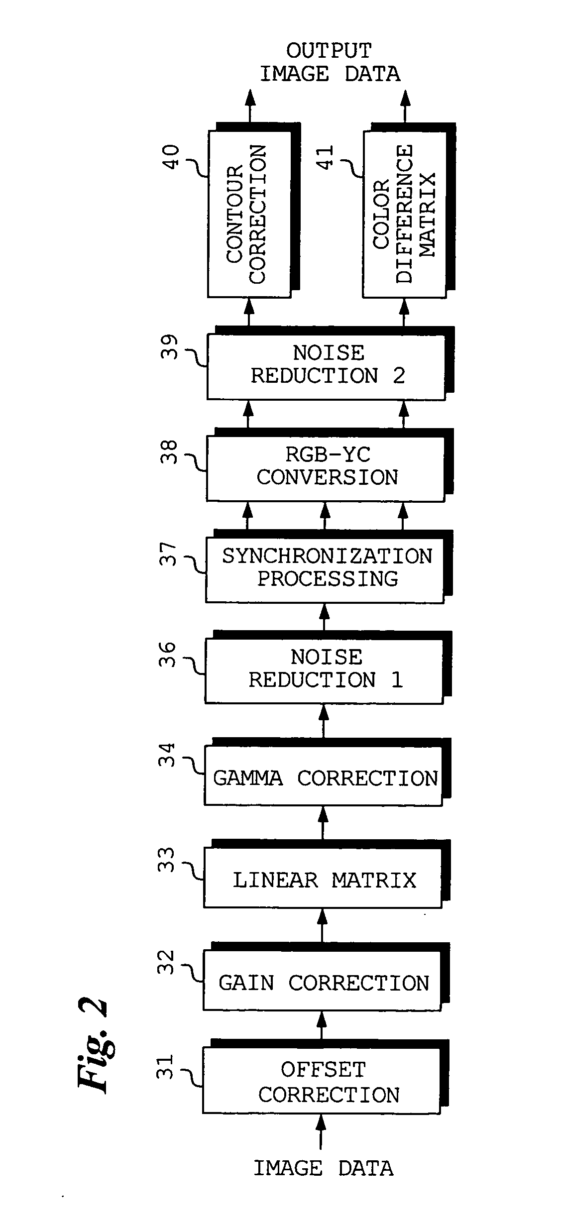
[0011] In accordance with the present invention, uncorrelated noise is removed from color image data that prevails before the application of color interpolation processing thereto. Since color interpolation processing has not been applied to this color image data, removal of uncorrelated noise can be performed effectively. Further, color image data that has been subjected to color interpolation processing undergoes noise removal without relation to uncorrelated noise. As a result, it is possible to remove noise of a specific frequency component. Since noise removal that conforms to the characteristics of the image data is performed rather than simply performing noise removal a plurality of times, highly effective noise removal can be realized.

Problems solved by technology

The influence of noise, therefore, has become a problem.
Although there is prior art wherein noise reduction processing is executed multiple times (see the specification of Japanese Patent Application Laid-Open No. 2003-141531), there are instances where effective noise reduction cannot be performed merely by executing processing multiple times.

Method used


Image

  • Noise reduction apparatus, method and program
  • Noise reduction apparatus, method and program
  • Noise reduction apparatus, method and program

Examples


Embodiment Construction

[0031] A preferred embodiment of the present invention will now be described in detail with reference to the drawings.

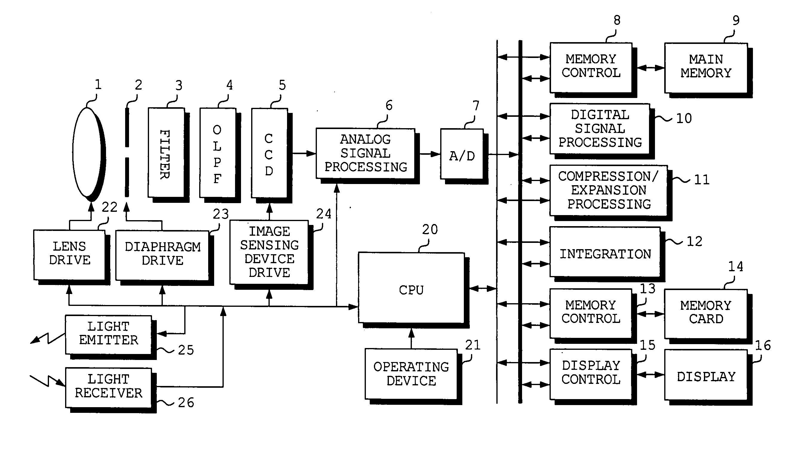
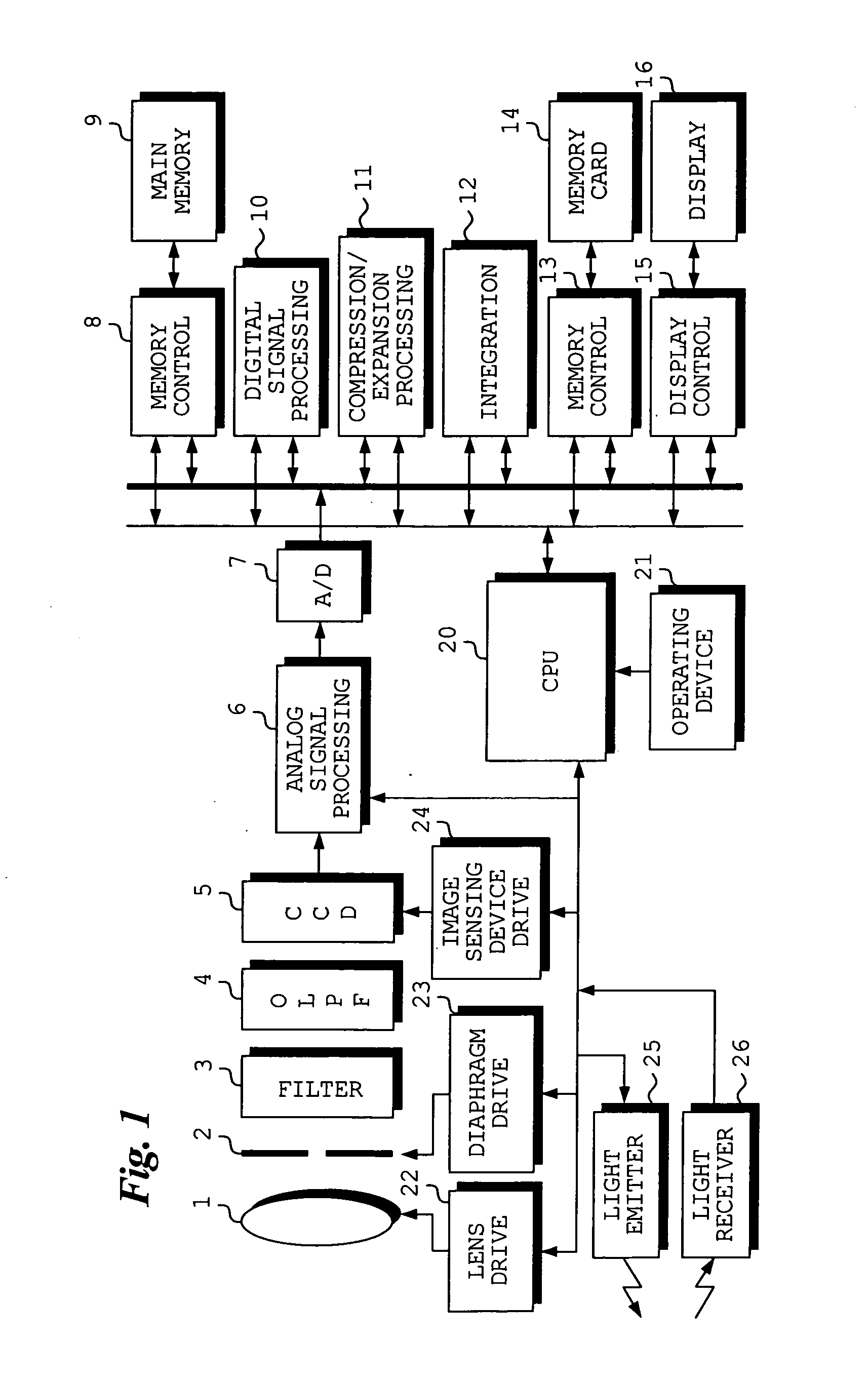
[0032]FIG. 1 is a block diagram illustrating the electrical structure of a digital still camera according to an embodiment of the present invention.

[0033] The operation of the overall digital still camera is controlled by a CPU 20.

[0034] The digital still camera includes an operating device 21 having a shutter-release button of two-step stroke type and a mode setting dial for setting an image sensing mode, a playback mode and a picture-taking scene. An operating signal that is output from the operating device 21 is input to the CPU 20. Further, the digital still camera is capable of flash photography and includes an electronic-flash light-emission circuit 25. Light that emerges from the electronic-flash light-emission circuit 25 illuminates a subject, whereupon light reflected from the subject is received by a light-receiving circuit 26. The amount of light emitte...


PUM


Abstract

CCD-RAW data obtained by sensing the image of a subject is applied to a first noise reduction circuit via a offset correction circuit, a gain correction circuit, a linear matrix circuit and a gamma correction circuit. Uncorrelated noise is removed from the CCD-RAW data in the first noise reduction circuit. The CCD-RAW data is subjected to synchronization (color interpolation) in the synchronization processing circuit, and luminance data Y and color difference data C is generated by an RGB-YC conversion circuit. The generated luminance data Y and generated color difference data C is subjected to noise reduction processing on a per-frequency-component basis in the second noise reduction circuit. Suitable noise reduction processing conforming to the state of image data before and after synchronization processing is executed.

Description

BACKGROUND OF THE INVENTION [0001] 1. Field of the Invention [0002] This invention relates to a noise reduction apparatus and method and to a noise reduction program. [0003] 2. Description of the Related Art [0004] CCDs used in digital still cameras are continuing to be improved in terms of number of pixels and sensitivity. The influence of noise, therefore, has become a problem. [0005] Although there is prior art wherein noise reduction processing is executed multiple times (see the specification of Japanese Patent Application Laid-Open No. 2003-141531), there are instances where effective noise reduction cannot be performed merely by executing processing multiple times. SUMMARY OF THE INVENTION [0006] Accordingly, an object of the present invention is to reduce noise effectively. [0007] According to the present invention, the foregoing object is attained by providing a noise reduction apparatus comprising: a first noise removal device (first noise removal means) for inputting colo...

Claims


Application Information

Patent Timeline
Patent Type & Authority Applications(United States)
IPC IPC(8): H04N5/217H04N5/21H04N23/12H04N23/40H04N25/00H04N101/00
CPCH04N9/045H04N5/357H04N25/60H04N23/843H04N25/134
Inventor TAMARU, MASAYATAKEMURA, KAZUHIKOOOISHI, MAKOTOHAYASHI, KENKICHITANAKA, SEIJI
Owner FUJIFILM CORP
Learn More