
Liquid crystal display device

a liquid crystal display and display device technology, applied in non-linear optics, instruments, optics, etc., can solve the problems of increasing the burden on light source units, increasing the time taken for use, and unable to diversified configuration so as to simplify the maintenance of liquid crystal display devices

Inactive Publication Date: 2006-02-23
PANASONIC LIQUID CRYSTAL DISPLAY CO LTD +1
View PDF5 Cites 13 Cited by
  • Summary
  • Abstract
  • Description
  • Claims
  • Application Information

AI Technical Summary

Benefits of technology

"The invention aims to address issues in the production and maintenance of liquid crystal display devices used in commercial products such as computers and televisions. The invention provides a common solution for parts and types of liquid crystal display devices, which can be used stably and flexibly by computer and television manufactures. The invention also simplifies maintenance and prevents damage to the display during transportation. The technical effects of the invention include reducing breakage of liquid crystal display devices, simplifying maintenance and preventing dust and particles from entering the display."

Problems solved by technology

More specifically, under circumstances, in which these commercial products are produced in various kinds and small quantity, liquid crystal display devices cannot but be diversified in configuration.
More specifically, an increase in time taken in using the above-mentioned computer products in use in offices and personal use has increased burdens on light source units, in particular, cold-cathode fluorescent tubes used therefor, of liquid crystal display devices to cause unexpected deterioration of these parts.

Method used


Image

  • Liquid crystal display device
  • Liquid crystal display device
  • Liquid crystal display device

Examples


Embodiment Construction

[0035] An explanation will be given below to an embodiment of the invention with reference to the drawings. In addition, parts having the same function are designated by the same characters in the drawings illustrated below, and reiteration of the explanation is omitted.

[0036] (Entire Constitution of an Liquid Crystal Display Device)

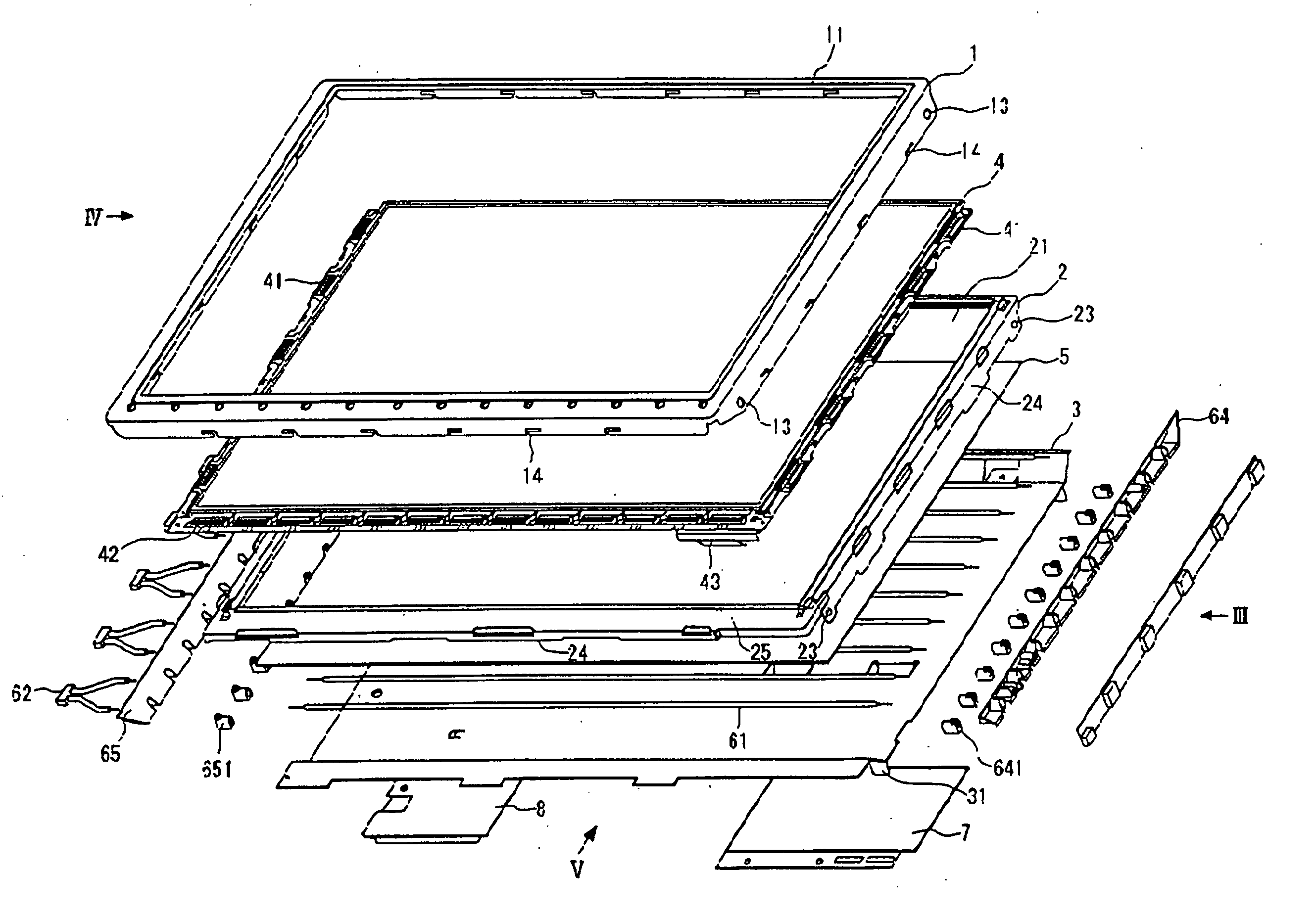
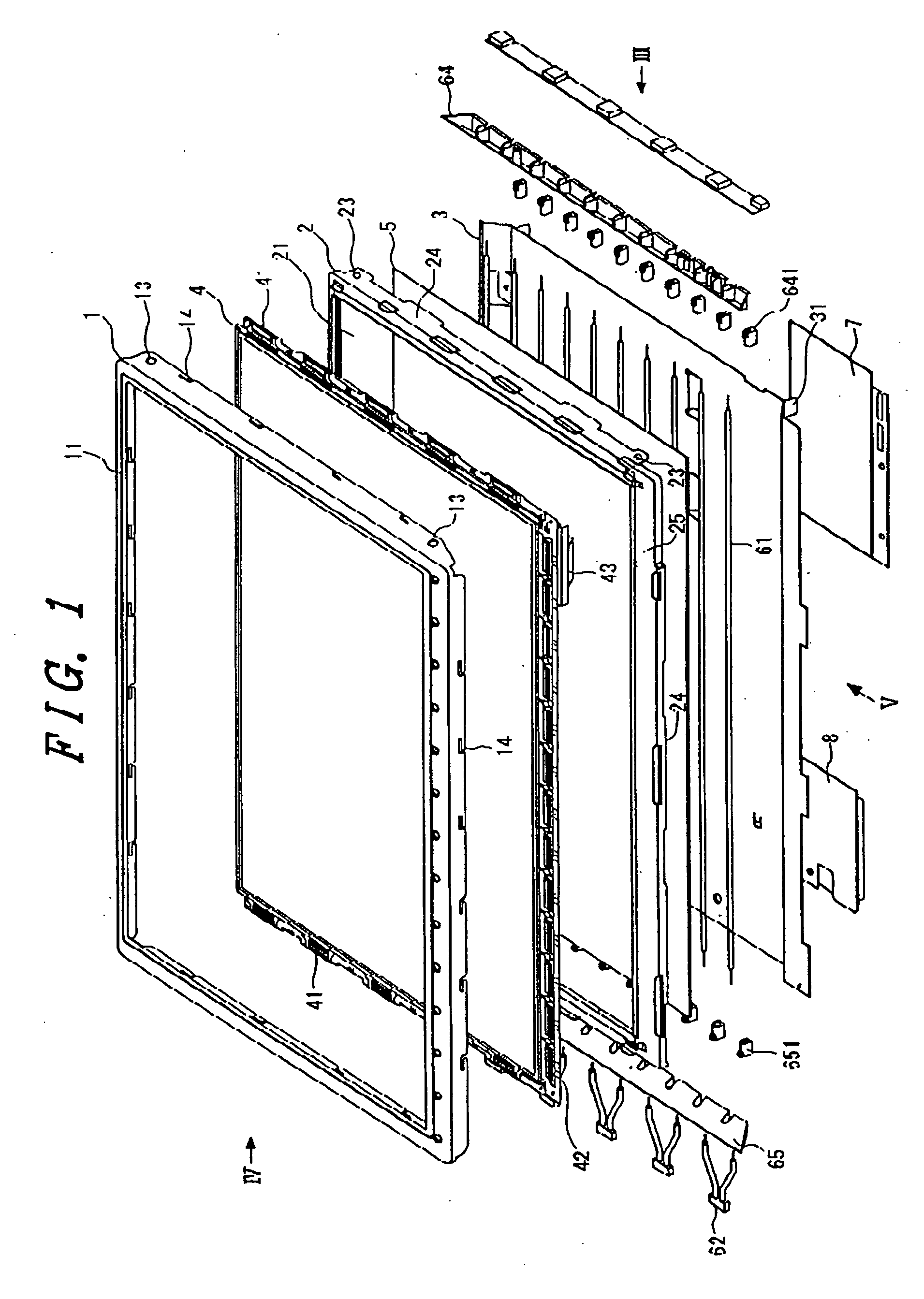
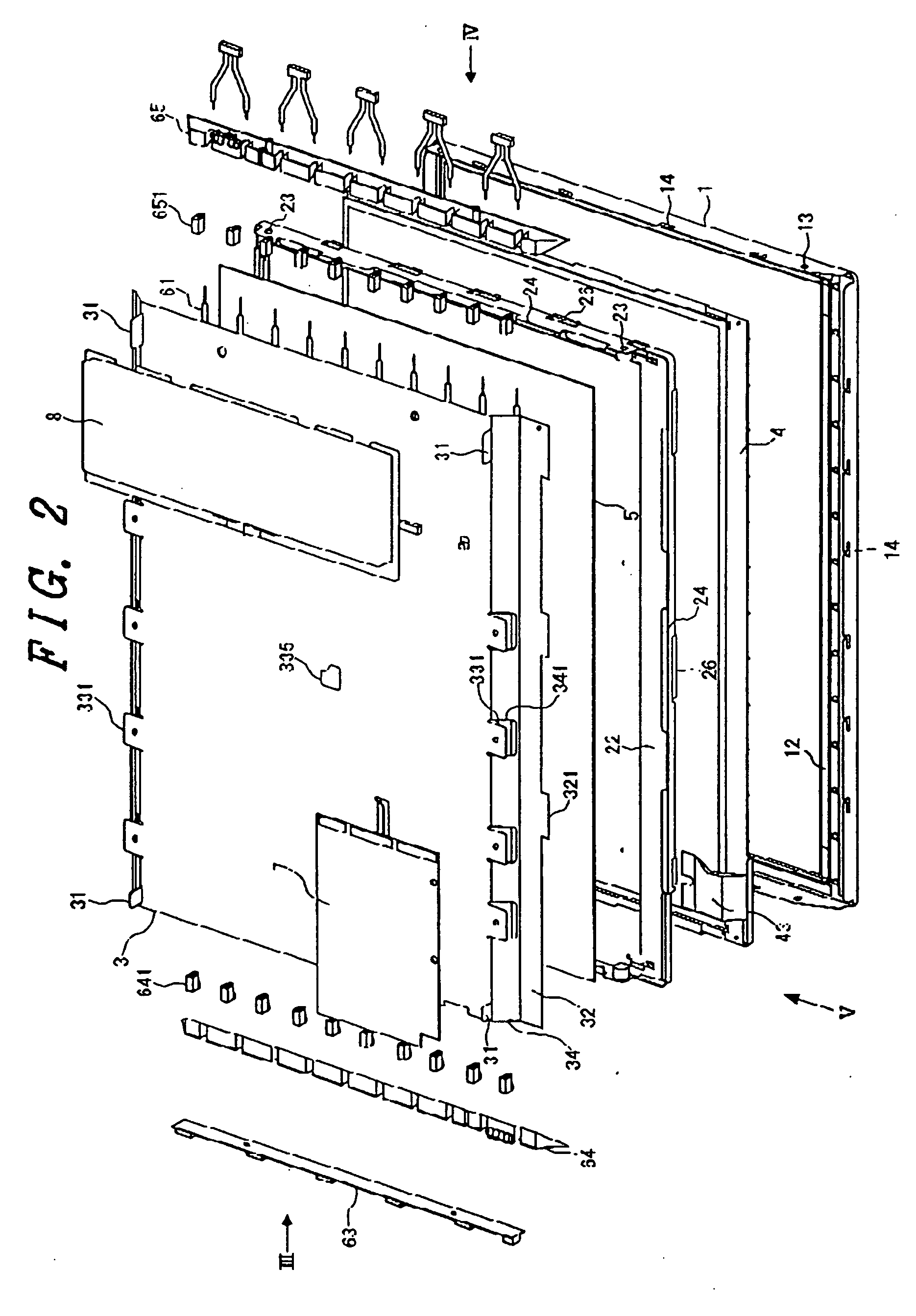
[0037]FIGS. 1 and 2 are exploded, perspective views showing a liquid crystal display device according to the invention.

[0038]FIG. 1 is a perspective view from a side of a liquid crystal display panel (a front side of the liquid crystal display device relative to a user's visual field), and FIG. 2 is a perspective view from a side opposite to FIG. 1 (aback side of the liquid crystal display device relative to a user's visual field).

[0039] In FIG. 1, the reference numeral 1 designates a first housing, 2 second housing 2,3 a third housing, 4 a liquid crystal display panel, 5 an optical sheet (a diffusion film on an optical source side, and a prism film ...


PUM

PropertyMeasurementUnit
AC voltageaaaaaaaaaa
voltageaaaaaaaaaa

Abstract

The object of the present invention is to make parts and kinds of liquid crystal display devices in common for cope stably and flexibly with commercial products of computer makers and television makers which have been promoted in various kinds, for simplifying maintenance of a liquid crystal display unit mounted on computers, display monitors therefor or televisions, and preferably for enabling to omit positional adjustment of a light source unit and a liquid crystal display panel during the maintenance of the liquid crystal display device. For this object, the invention provides a liquid crystal display device comprising first, second, and third housings, a liquid crystal display panel fixed between the first and second housings, a light source (cold-cathode fluorescent tubes) fixed to the third housing, the second and third housings being detachable to one another, being constructed by overlapping the first, second and third housings with each other, wherein a timing-converter board fixed to an opposite side surface of the third housing to a side surface to which the light source is fixed, and protrusions formed on the opposite side surface so as to determine a maximum thickness of the liquid crystal display device.

Description

CROSS-REFERENCE TO RELATED APPLICATION [0001] The present application is a Continuation of U.S. application Ser. No. 09 / 671,429 filed on Sep. 27, 2000, and claims priority from U.S. application Ser. 09 / 671,429 filed on Sep. 27, 2000, which claims priority to Japanese Patent Application 11-278811 filed on Sep. 30, 1999, the contents of which are hereby incorporated by reference into this application.BACKGROUND OF THE INVENTION [0002] 1. Field of the Invention [0003] The invention relates to a liquid crystal display device used for a monitor for laptop personal computers, desktop computers or the like, and a liquid crystal display monitor using the same. [0004] 2. Description of the Related Art [0005] Liquid crystal display devices have become widespread as monitors for laptop personal computers and desktop computers. [0006] In such products, a liquid crystal display device is mounted as a liquid crystal display module including in combination a liquid crystal display panel and a ligh...

Claims


Application Information

Patent Timeline
Patent Type & Authority Applications(United States)
IPC IPC(8): G02F1/1333G02F1/13G02F1/1335G02F1/13357
CPCG02F1/133308G02F1/133608G02F1/133604G02F1/1335
Inventor MORISHITA, SHUNSUKEENDOU, SHUUSUKE
Owner PANASONIC LIQUID CRYSTAL DISPLAY CO LTD
Learn More