Vlan protocol

a virtual local area network and protocol technology, applied in the field of virtual local area network (vlan) protocols, can solve problems such as inability to communicate with each other

Inactive Publication Date: 2006-02-23
MARVELL ISRAEL MISL
View PDF6 Cites 32 Cited by
  • Summary
  • Abstract
  • Description
  • Claims
  • Application Information

AI Technical Summary

Problems solved by technology

Thus, if end nodes of the same switch are part of different VLANs, they will not be able to communicate with each other.

Method used


Image

  • Vlan protocol
  • Vlan protocol
  • Vlan protocol

Examples


Embodiment Construction

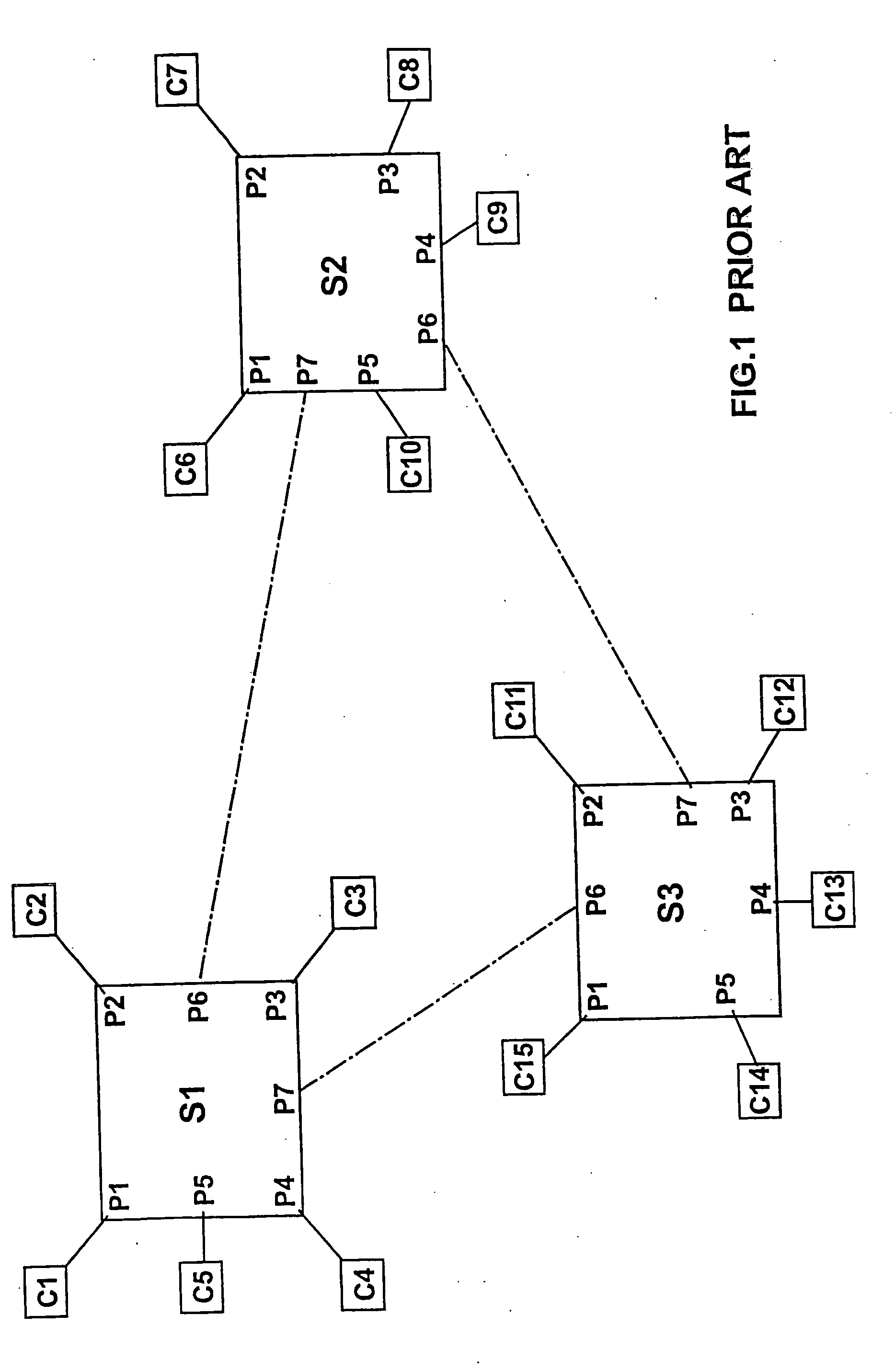
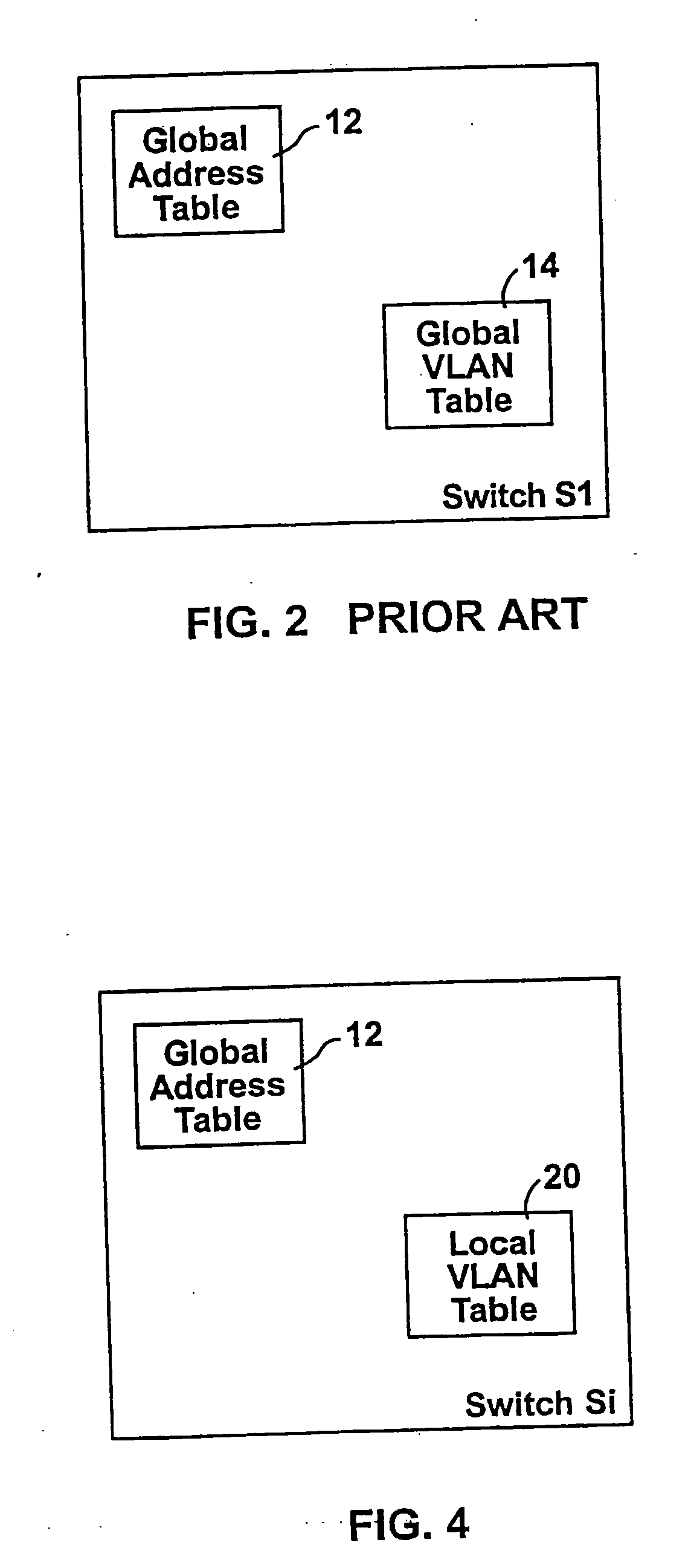
[0029] Reference is now made to FIG. 4 which illustrates a switch, constructed and operative in accordance with a preferred embodiment of the present invention, having local VLAN tables 20 and to FIGS. 5A, 5B and 5C which illustrate, in general terms, local VLAN tables 20A, 20B and 20C, respectively. FIGS. 5A, 5B and 5C are the local VLAN tables stored, in accordance with a preferred embodiment of the present invention, in switches S1, S2, and S3, respectively, of the network of FIG. 1.

[0030] As indicated in FIG. 4, each switch S has a global address table 12, as in the prior art. However, in accordance with a preferred embodiment of the present invention, each switch S replaces the global VLAN table of the prior art with a local VLAN table 20.

[0031] As shown in FIGS. 5A, 5B and 5C, each local VLAN table 20 lists the VLAN identifier (id) 22 of each VLAN, the local ports 24 belonging to that VLAN id and the other switches 26 of the network which also have ports belonging to that VL...


PUM


Abstract

A generally full-wire throughput, switching Ethernet controller used within an Ethernet network of other switching Ethernet controllers connected together by a bus. The controller comprises a plurality of ports including at least one bus port associated with ports connected to other switching Ethernet controllers. A hash table stores MAC addresses and VLAN ids of ports within said Ethernet network. A hash table address control hashes the MAC address and VLAN id of a packet to initial hash table location values, changes the hash table location values by a fixed jump amount if the address and VLAN id values stored in said initial hash table location do not match the received address and VLAN id, and provides at least an output port number of the port associated with the received address and VLAN id. A storage buffer includes a multiplicity of contiguous buffers in which to temporarily store said packet.

Description

CROSS-REFERENCE TO RELATED APPLICATIONS [0001] This application is a Divisional application of U.S. patent application Ser. No. 10 / 293,098, filed Nov. 12, 2002, which is a continuation of application Ser. No. 09 / 348,864 filed on Jul. 7, 1999, the contents of which are incorporated herein by reference.FIELD OF THE INVENTION [0002] The present invention relates to virtual local area networks (VLAN) protocols in general. BACKGROUND OF THE INVENTION [0003] A network switch creates a local area network (LAN) among a plurality of end nodes, such as workstations, and other network switches connected thereto. Each end node is connected to one port of the network. The ports also serve to connect network switches together. [0004] Each end node sends packets of data to the network switch which the switch then routes either to another of the end nodes connected thereto or to a network switch to which the destination end node is connected. In the latter case, the receiving network switch routes ...

Claims


Application Information

Patent Timeline
Patent Type & Authority Applications(United States)
IPC IPC(8): H04L12/56G06F15/173H04J3/26H04LH04L12/28H04L12/46H04L45/74
CPCH04L12/4641H04L12/467H04L29/12801H04L61/6022H04L45/745H04L61/6004H04L29/12839H04L2101/604H04L2101/622
Inventor MEDINA, EITANSHEMLA, DAVID
Owner MARVELL ISRAEL MISL
Why Eureka
Try Eureka