Ram-incorporated driver, and display unit and electronic equipment using the same

a technology of ram and driver, which is applied in the direction of static indicating devices, instruments, high-level techniques, etc., can solve the problems of increasing time-related restrictions on the operation of the microprocessor unit (mpu) for controlling circuits, display units, and moving images displayed on the display section that are even more complex, so as to reduce the load on the mpu and increase the operating efficiency of the mpu

Inactive Publication Date: 2006-05-23
SEIKO EPSON CORP
View PDF24 Cites 28 Cited by
  • Summary
  • Abstract
  • Description
  • Claims
  • Application Information

AI Technical Summary

Benefits of technology

[0025]Since this electronic equipment and this display unit reduce the load on the MPU during the display of ...

Problems solved by technology

However, the rewriting of still-image data in the still-image storage area of the RAM periodically uses the bus line over which the moving-image data is being transferred, so it is only possible to use the gap between the transfer of one screen of moving-image data and the transfer of the next screen of moving-image data therefor.
In this manner, the transfer of still-image data within the limited times between screens of moving-image data can restrict the operating time in which the MPU can supply moving-image data and still-image data to the display un...

Method used


Image

  • Ram-incorporated driver, and display unit and electronic equipment using the same
  • Ram-incorporated driver, and display unit and electronic equipment using the same
  • Ram-incorporated driver, and display unit and electronic equipment using the same

Examples


first embodiment

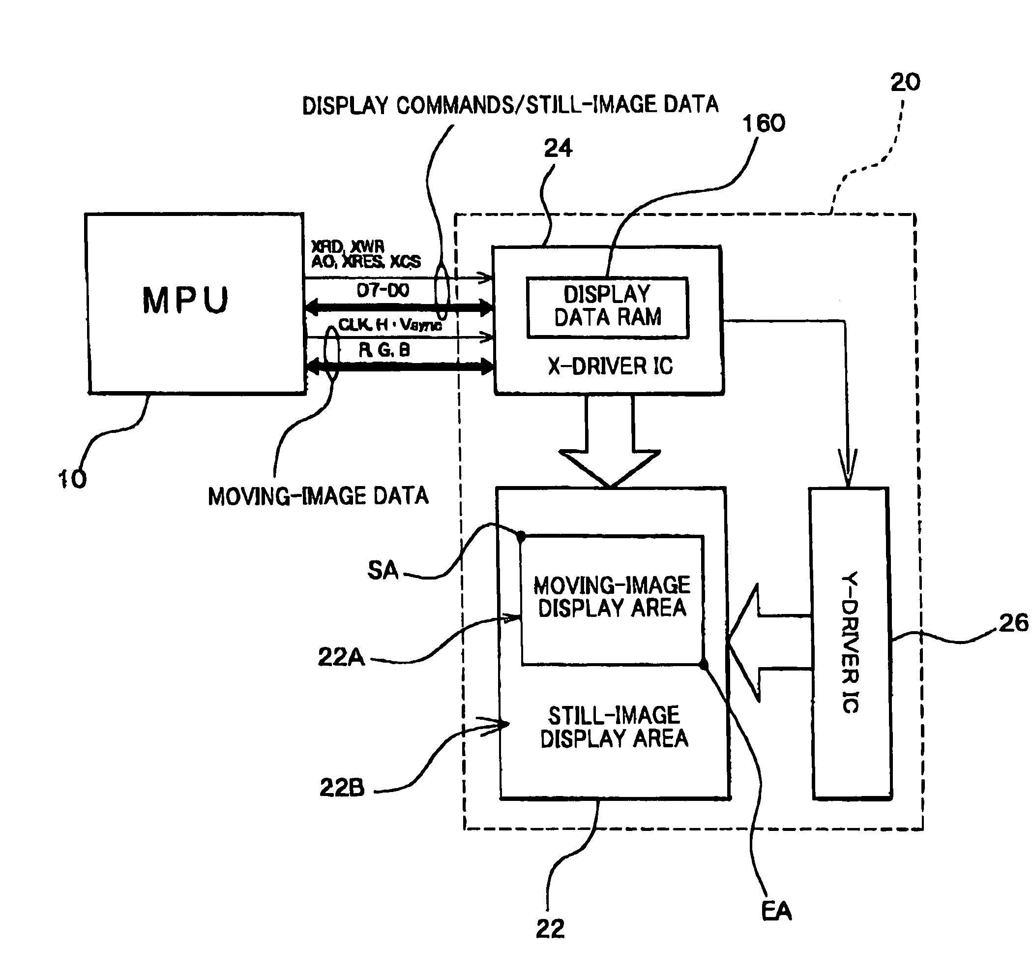
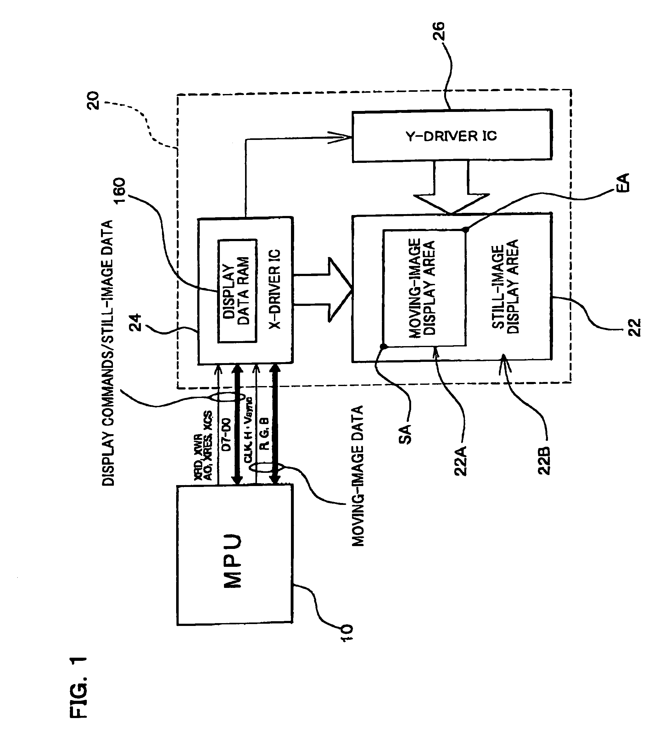
[0046]the present invention is described below with reference to FIGS. 1 to 7. FIG. 1 is a schematic block diagram of electronic equipment to which the present invention is applied. In FIG. 1, this electronic equipment is configured of a microprocessor unit (MPU) 10 and a display unit 20. The display unit 20 has a matrix panel having electro-optical elements, such as a color liquid crystal panel 22, a RAM-incorporated X-driver IC 24 for driving this liquid crystal panel 22, and a Y-driver IC 26 for scanning.

[0047]The matrix panel 22 could be one that uses a liquid crystal having optical characteristics that change on the application of a voltage, and other electro-optical elements. For example, the liquid crystal panel 22 could be configured of a simple matrix panel in which a liquid crystal is sealed between a first substrate on which is formed a plurality of segment electrodes (first electrodes) and a second substrate on which is formed a common electrode (second electrode). The l...

second embodiment

[0090]FIG. 8 shows an exemplary block diagram of part of an X-driver IC 300 in accordance with the present invention Note that circuits in FIG. 8 that have the same functions as circuits in FIG. 4 are denoted by the same reference numbers and further description thereof is omitted. The circuits omitted from FIG. 8 are the same as those of FIG. 4.

[0091]The first way in which the X-driver IC 300 of FIG. 8 differs from the X-driver IC 24 of FIG. 4 is the provision of first and second display data RAMs 310 and 320. Still-image data is stored in the first RAM 310 and moving-image data is stored in the second RAM 320. Note that the first and second RAM portions 310 and 320 do not need the second word line W2, the second bit line pair B2 and / B2, the second column switch SW2, the second column address decoder 144A, and the second page address decoder 154A of FIG. 6, so memory cells of a prior-art configuration can be used therefore.

[0092]The relationships between a still-image storage area...

third embodiment

[0099]In such a case, a RAM-incorporated driver IC 420 in accordance with the present invention makes it possible to suppress any enlargement of the wiring area and number of terminals for the signals to be transferred, by supplying moving-image data from the MPU over a high-speed serial transfer line, and also enables writing of still-image data and moving-image data by separate systems.

[0100]In this case, a high-speed serial transfer line is a transfer line that enables high-speed transfer of data in serial form as a differential signal, where differential amplification is performed on the reception side. Various standards have been proposed for such a high-speed serial transfer line, such as the TIA-644 or EIA-644 of the Telecommunications Industry Association or the Electronic Industries Association, the IEEE 1596.3 of the Institute of Electrical and Electronics Engineers, the low voltage differential signaling (LVDS) standard, the IEEE 1394, or the universal serial bus (USB) st...


PUM


Abstract

The present invention provides a RAM-incorporated driver that enables the writing of moving-image data to a RAM simultaneously with the writing of still-image data to a RAM, at a reduced energy consumption. The RAM incorporated X-driver IC receives still-image data from an MPU and moving-image data that is input by a separate system through a high-speed serial transfer line in accordance with the LVDS standard. An LVDS reception circuit suppresses the consumption of a steady current by which the differential input receiver operates, based on a data validation signal that becomes active when transfer data on the high-speed serial data transfer line from the MPU becomes valid. The still-image data and moving-image data that is received by separate systems is written to a RAM through first and second bus lines, respectively. Reading of still-image data and moving-image data, which is stored in a RAM, as display data is controlled by a display address control circuit.

Description

BACKGROUND OF THE INVENTION[0001]Japanese Patent Application No. 11-338146, filed Nov. 29. 1999, is hereby incorporated by reference in its entirety. Japanese Patent Application No. 2000-211079, filed Jul. 12, 2000, is hereby incorporated by reference in its entirety. International Application No. PCT / JP00 / 08384, filed Nov. 29, 2000 is hereby incorporated by reference in its entirety.[0002]1. Field of Invention[0003]The present invention relates to a RAM-incorporated driver that drives the display of still and moving images on one screen, together with a display unit and electronic equipment that uses the same.[0004]2. Description of Related Art[0005]Recent advances in communications and packaging technology have made it possible to display various types of highly informative data on a display section of a portable electronic equipment. The data can include not only character text consisting of numerals and characters, but also more complex data, such as still and moving images.[000...

Claims


Application Information

Patent Timeline
IPC IPC(8): G09G3/36G06F12/00G06F3/147G09G3/20G09G5/00G09G5/36G09G5/39G09G5/393G09G5/397G11C7/16H04M1/72439
CPCG06F3/147G09G3/3611G09G3/3685G09G5/006G09G5/36G11C7/16H04M1/72555G09G5/39G09G5/393G09G5/397G09G2310/0221G09G2320/0261G09G2330/021G11C2207/16G09G3/2014H04M1/72439Y02D30/70G02F1/133
Inventor TAMURA, TSUYOSHI
Owner SEIKO EPSON CORP
Why Eureka
Try Eureka