Method and apparatus for estimating SFO in digital receiver

a digital receiver and receiver technology, applied in the field of digital receivers, can solve the problems of receivers not being able to demodulate reception signals, distortion of reception signals, and very weak resistance of dm transmission schemes to synchronization, so as to reduce jittering range

Inactive Publication Date: 2006-02-23
LG ELECTRONICS INC
View PDF4 Cites 15 Cited by
  • Summary
  • Abstract
  • Description
  • Claims
  • Application Information

AI Technical Summary

Benefits of technology

[0024] Another object of the present invention is to provide an SFO estimation method for reducing a jittering range caused by overshoots in a frequency tracking mode.
[0040] Therefore, the present invention correctly estimates the SFO value using the scattered pilot as compared to the conventional estimation method based on a CP, and reduces a jittering range caused by overshoots using a zero-forcing algorithm, such that it solves an SFO estimation failure caused by serious phase distortion.

Problems solved by technology

On the other hand, the OFDM transmission scheme has very weak resistance to synchronization.
Therefore, if accurate synchronization is not established between a transmitter and a receiver, distortion of a reception signal occurs.
Particularly, if the receiver does not correctly perform sampling synchronization, an ISI (Inter Symbol Interference) and a constellation rotation may occur in a reception signal, such that the receiver cannot demodulate the reception signal.
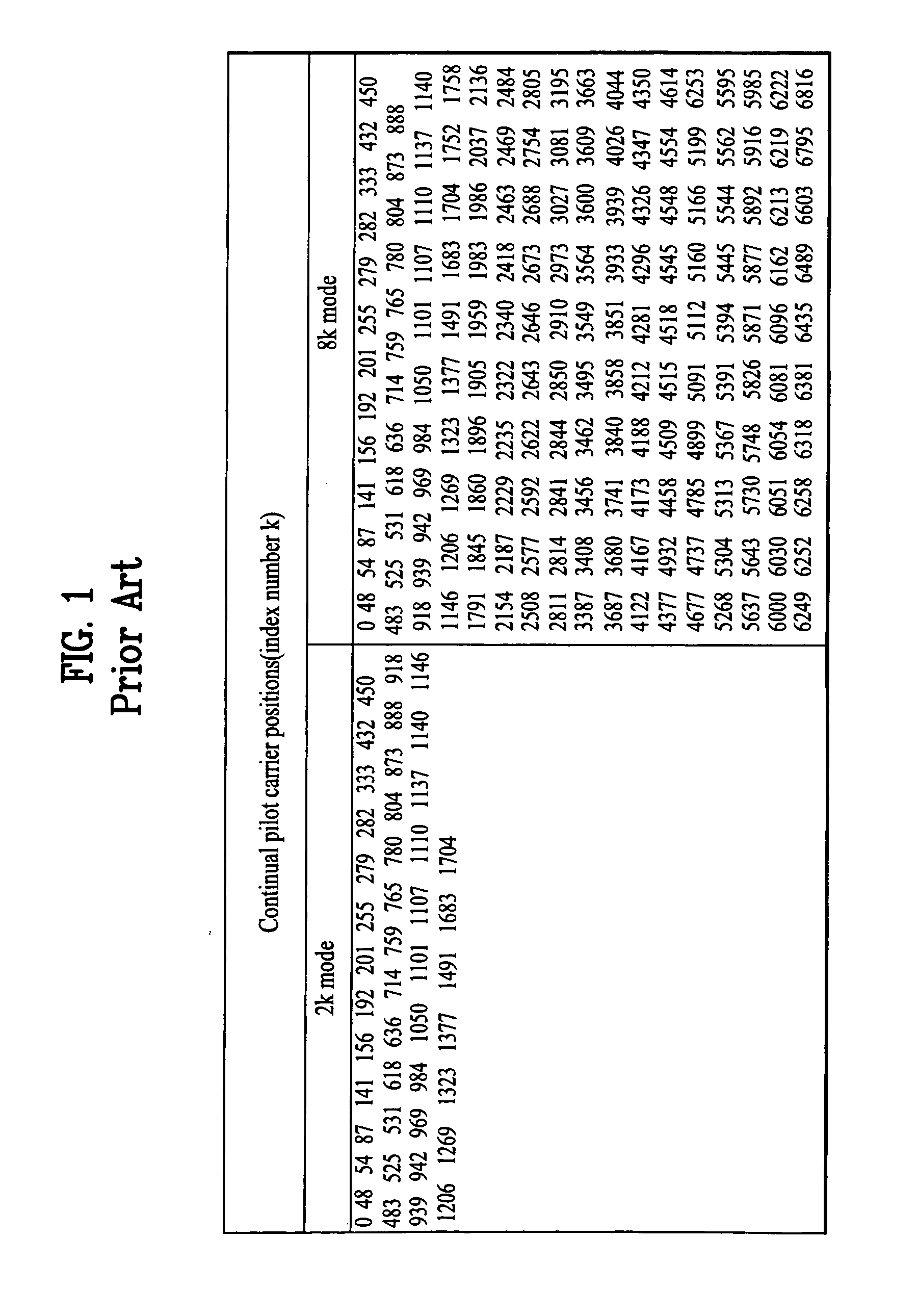
However, the above-mentioned SFO estimation method may incur SFO estimation complexity due to irregular overshoots of the CP, and may have difficulty in acquiring sufficient phase information due to the above-mentioned limited number of continual CPs (i.e., 45 phase data units in the 2k mode, and 177 phase data units in the 8k mode).
Particularly, the conventional SFO estimation method has difficulty in estimating a correct SFO when irregular overshoots occur due to a deep fading phenomenon.

Method used


Image

  • Method and apparatus for estimating SFO in digital receiver
  • Method and apparatus for estimating SFO in digital receiver
  • Method and apparatus for estimating SFO in digital receiver

Examples


Embodiment Construction

[0054] Reference will now be made in detail to the preferred embodiments of the present invention, examples of which are illustrated in the accompanying drawings. Wherever possible, the same reference numbers will be used throughout the drawings to refer to the same or like parts.

[0055] Prior to describing the present invention, it should be noted that most terms disclosed in the present invention correspond to general terms well known in the art, but some terms have been selected by the applicant as necessary and will hereinafter be disclosed in the following description of the present invention. Therefore, it is preferable that the terms defined by the applicant be understood on the basis of their meanings in the present invention.

[0056]FIG. 4 shows a pilot insertion pattern according to the present invention;

[0057] Pilot arrangement shown in FIG. 4 is indicative of a predetermined pattern prescribed in a DVB-H transmission standard. The above-mentioned pilot arrangement is lar...


PUM


Abstract

A method and apparatus for estimating a sampling frequency offset (SFO) in a digital receiver is disclosed. The method for estimating the SFO in the digital receiver to perform sampling synchronization includes the steps of: a) extracting a current scattered pilot contained in a single OFDM (Orthogonal Frequency Division Multiplexing) symbol interval; b) calculating a phase value using both the extracted current scattered pilot and a delay value acquired when the current scattered pilot is delayed by four symbol intervals; and c) estimating an SFO value using the calculated phase value. Therefore, the method correctly estimates the SFO value using the scattered pilot as compared to a conventional estimation method based on a continual pilot (CP), and reduces a jittering range caused by overshoots using a zero-forcing algorithm, such that it solves an SFO estimation failure caused by serious phase distortion.

Description

CROSS REFERENCE TO RELATED APPLICATIONS [0001] Pursuant to 35 U.S.C. § 119(a), this application claims the benefit of earlier filing date and right of priority to Korean Patent Application No. 10-2004-0065130, filed on Aug. 18, 2004, the content of which is hereby incorporated by reference herein in its entirety. BACKGROUND OF THE INVENTION [0002] 1. Field of the Invention [0003] The present invention relates to a digital receiver, and more particularly, to a method and apparatus for estimating an SFO (Sampling Frequency Offset) applicable to an OFDM (Orthogonal Frequency Division Multiplexing) digital receiver. [0004] 2. Discussion of the Related Art [0005] Generally, a DVB-T (Digital Video Broadcasting-Terrestrial) system and a DVB-H (DVB-Handheld) system, which act as the European transmission standard for terrestrial digital TV have generally selected an OFDM (Orthogonal Frequency Division Multiplexing) transmission scheme. It is well known in the art that the OFDM transmission ...

Claims


Application Information

Patent Timeline
Patent Type & Authority Applications(United States)
IPC IPC(8): H04L7/00H04K1/10
CPCH04L5/0048H04L27/2675H04L27/2657H04N7/015
Inventor LEE, DONG GEUNLEE, TAE WON
Owner LG ELECTRONICS INC
Why Eureka
Try Eureka