Tapping screw

a technology of screw and screw head, which is applied in the direction of screws, threaded fasteners, fastening means, etc., can solve the problems of large thrust and screwing torque, the screw cannot be fastened to the partner steel plate, and the screw is difficult to precisely thread in the prepared hole, etc., to achieve the effect of improving the shape accuracy of the notch portion, reducing the contact area of the screw thread bitten into the prepared hole of the attached member, and improving the biting property

Inactive Publication Date: 2006-02-23
AOYAMA SEISAKUSHO CO LTD
View PDF66 Cites 20 Cited by
  • Summary
  • Abstract
  • Description
  • Claims
  • Application Information

AI Technical Summary

Benefits of technology

[0010] In the invention of claim 4, the corner portion is formed at the diametrical outside end of the rising wall. The corner portion pushes and widens the prepared hole by biting onto the circumferential face of the prepared hole. The screw thread and the notch portion are molded by form rolling. Thus, the shape accuracy of the notch portion is improved and the corner portion is formed in a clear and sharp shape. Therefore, the biting property of the screw thread with respect to the prepared hole of the attached member is improved. Thus, the female screw is reliably formed in the prepared hole of the attached member. Further, in the screw thread, the corner portion mainly comes in contact with the circumferential face of the prepared hole in the notch portion. Therefore, the contact area of the screw thread bitten into the prepared hole of the attached member is reduced. Accordingly, the screwing torque is reduced and the tapping screw can be easily screwed into the prepared hole of the attached member. Further, the screw thread is easily molded by molding the notch portion by form rolling. Accordingly, productivity can be improved.
[0011] In the invention of claim 5, the stem portion is formed from a position moved a predetermined angle a from the corner portion on the backward side in the rotating direction to the end portion of the rising wall on its diametrical inside. Therefore, the contact area of the screw thread with respect to the prepared hole of the attached member is reduced. Accordingly, the screwing torque is reduced and the tapping screw can be easily screwed into the prepared hole of the attached member.
[0012] In the invention of claim 6, 7 or 8, the screw thread is left in the specific area. Namely, the notch portion is formed by notching one portion of the screw thread. Therefore, in comparison with a case in which the screw thread is deeply notched, the screw thread and the notch portion are easily formed, and the life of a form rolling die is extended. Further, since the notch portion is formed by the form rolling, the corner portion is formed in a clear and sharp shape. As a result, the biting property of the screw thread with respect to the prepared hole of the attached member is improved. Thus, the female screw is reliably formed in the prepared hole of the attached member. Accordingly, the screwing torque is reduced and the tapping screw can be easily screwed into the prepared hole of the attached member. Further, productivity can be improved since the screw thread and the notch portion are easily formed and the life of the form rolling die is extended.
[0013] In the invention of claim 9, the outer shape seen from the axial direction of the screw thread is set to be non-circular in the specific area of the screw thread continuously formed over the constant diameter portion and the reduced diameter portion. Further, with respect to the screw thread having the non-circular outer shape, the contact area with the circumferential face of the prepared hole of the attached member is reduced in the specific area. Accordingly, the screwing torque is reduced and the tapping screw can be easily screwed into the prepared hole of the attached member.
[0014] In the invention of claim 10, the outer shape of the constant diameter portion seen from the axial direction of the screw thread is set to be non-circular in a predetermined range in the axial direction from the boundary of the constant diameter portion and the reduced diameter portion. Thus, the contact area of the screw thread and the circumferential face of the prepared hole of the attached member is reduced in one portion of the constant diameter portion and the reduced diameter portion. Accordingly, the screwing torque is reduced and the tapping screw can be easily screwed into the prepared hole of the attached member. Further, after the reduced diameter portion is screwed into the prepared hole, the female screw of the same diameter as the constant diameter portion is threaded in the prepared hole in advance before the constant diameter portion is fastened. Accordingly, the constant diameter portion can be easily fastened.
[0015] In the invention of claim 11, the shape of the screw thread seen from its axial direction in the specific area is a square shape. Therefore, the top portion of the square screw thread is formed in a rising shape without being broken. Thus, the biting property of the screw thread with respect to the prepared hole of the attached member is improved. Accordingly, the female screw can be reliably formed in the prepared hole.

Problems solved by technology

However, in the above prior art, for example, when the screw thread forming the screw in the prepared hole is broken in fastening the tapping screw to a high tensile steel plate, etc., a problem exists in that the tapping screw cannot be fastened to the partner steel plate.
Further, when the screw thread of the non-circular outer shape is not completely pointed in the taper portion, it is difficult to precisely thread the screw in the prepared hole.
As a result, a problem exists in that large thrust and screwing torque are required when the portion of the screw thread that is not pointed is screwed and fastened to the prepared hole.

Method used


Image

  • Tapping screw
  • Tapping screw
  • Tapping screw

Examples


first embodiment

Mode

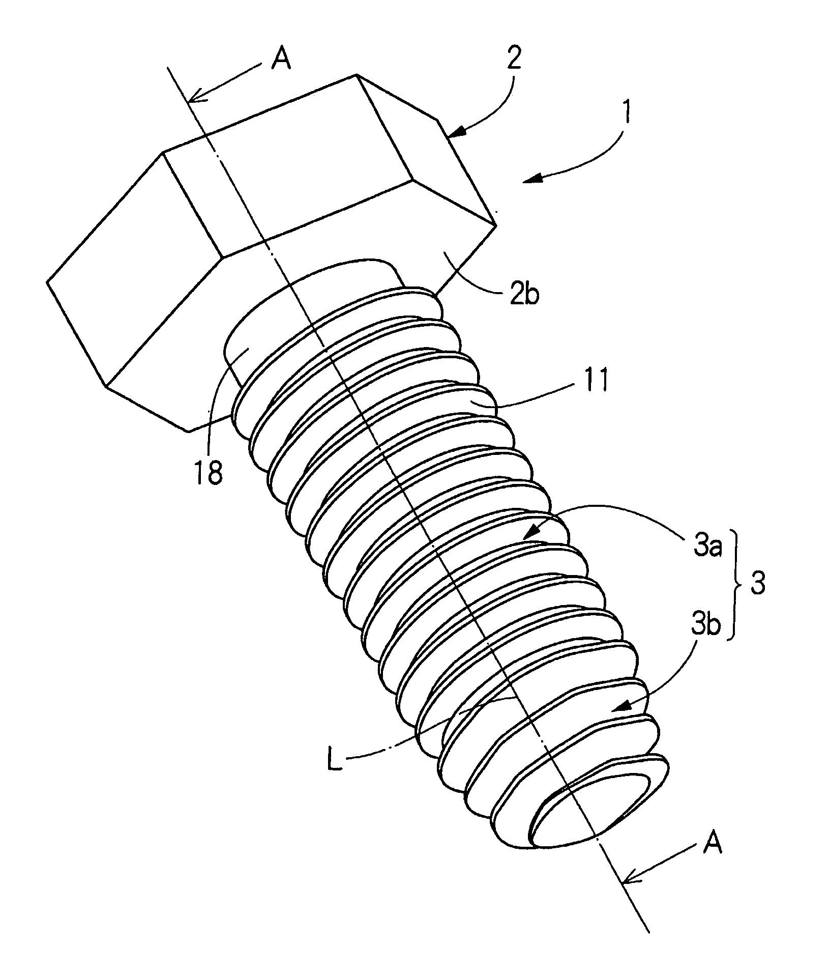
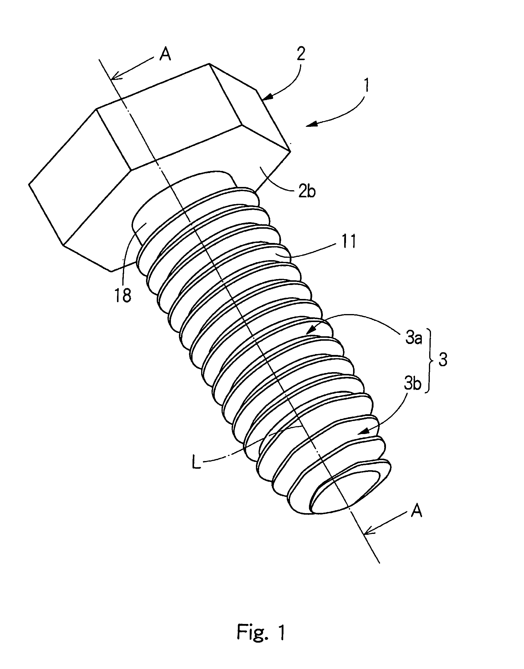
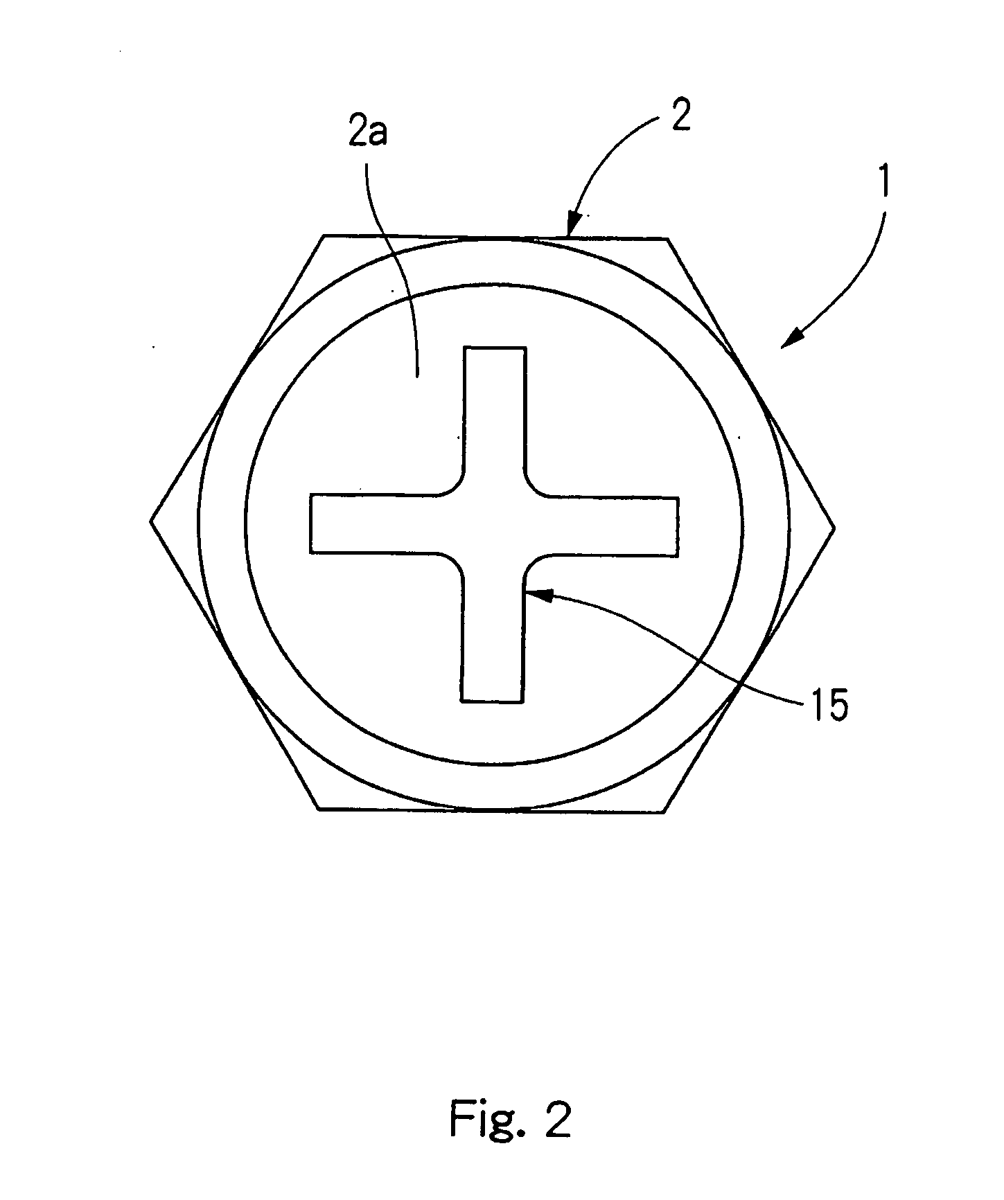
[0026] A first embodiment mode of a tapping screw embodying the present invention will be explained with reference to FIGS. 1 to 4. Here, the tapping screw of this embodiment mode is screwed into a prepared hole formed in an unillustrated attached member such as a steel plate, etc. so that the tapping screw is fastened to the attached member while a female screw is formed in that prepared hole. As shown in FIGS. 1 and 2, the tapping screw 1 is constructed by a head portion 2 of a hexagonal columnar shape, and a shaft portion 3 extending downward from the lower side face 2b of this head portion 2. In the tapping screw 1, both the head portion 2 and the shaft portion 3 extend along the common axis L. A cross hole 15 is formed on the upper face 2a of the head portion 2, and the tip of an unillustrated tool for transmitting torque to the tapping screw 1 is fitted into the cross hole 15. The shaft portion 3 is constructed by a constant diameter portion 3a approximately formed in a co...

second embodiment

Mode

[0030] A second embodiment mode of the tapping screw embodying the present invention will next be explained with reference to FIGS. 5 to 9. Here, the tapping screw of this embodiment mode is screwed into a prepared hole formed in an unillustrated attached member such as a steel plate, etc. so that the tapping screw is fastened to the attached member while a female screw is formed in that prepared hole.

[0031] First, the entire structure of the tapping screw 30 will be explained with reference to FIG. 5. As shown in FIG. 5, the tapping screw 30 is constructed by a head portion 32 of a hexagonal columnar shape, and a shaft portion 33 extending downward from the lower side face 32a of this head portion 32. In the tapping screw 30, both the head portion 32 and the shaft portion 33 extend along the common axis M. An unillustrated cross hole is formed on the upper face of the head portion 32, and the tip of a tool for transmitting torque to the tapping screw 30 is fitted into this cro...


PUM


Abstract

The tapping screw has a screw thread having a non-circular shape. Accordingly, when the tapping screw is screwed into the prepared hole formed in the attached member such as a steel plate, etc., the contact area of the screw thread and the circumferential face of the prepared hole of the attached member can be reduced in comparison with the screw thread having a circular outer shape. Accordingly, the screwing torque can be reduced. Further, since the top portion of the screw thread of the square outer shape has a rising shape without being broken, the biting property of the screw thread with respect to the prepared hole formed in the attached member is improved so that a female screw can be precisely threaded on the inner circumferential face of the prepared hole by the screw thread.

Description

TECHNICAL FIELD [0001] The present invention relates to a tapping screw, and particularly, relates to a tapping screw in which the outer shape of a screw thread seen from the axial direction is a non-circular shape. BACKGROUND ART [0002] A conventionally proposed tapping screw is screwed into a prepared hole formed in an attached member so that the tapping screw is fastened to this prepared hole while the tapping screw itself threads the screw. When the screw is threaded in the prepared hole by the tapping screw, the screw threading is advanced by hitting the top portion of the screw thread against the circumference face of the prepared hole. Here, it is publicly known that one portion of a shaft portion is formed in a tapering off shape, or the outer shape of the screw thread seen from its axial direction is a non-circular shape to more efficiently form the screw in the prepared hole. For example, various outer shapes such as a triangular shape (Japanese rice ball shape) having rou...

Claims


Application Information

Patent Timeline
Patent Type & Authority Applications(United States)
IPC IPC(8): F16B25/10F16B25/00F16B33/02
CPCF16B25/0021F16B25/0052F16B25/0047
Inventor MIZUNO, HIROMICHIHAMADA, MASAHIKOKOZAWA, MITSURUYAMADA, KENYA
Owner AOYAMA SEISAKUSHO CO LTD
Why Eureka
Try Eureka