Vascular filter with sleeve

Inactive Publication Date: 2006-02-23
CORDIS CORP
View PDF19 Cites 89 Cited by
  • Summary
  • Abstract
  • Description
  • Claims
  • Application Information

AI Technical Summary

Problems solved by technology

In addition, a vascular filter should preferably have a design whereby the filter is self-centering and stable in the

Method used


Image

  • Vascular filter with sleeve
  • Vascular filter with sleeve
  • Vascular filter with sleeve

Examples


Example

[0034] The following description of the preferred embodiments of the present invention is merely illustrative in nature, and as such it does not limit in any way the present invention, its application, or uses. Numerous modifications may be made by those skilled in the art without departing from the true spirit and scope of the invention.

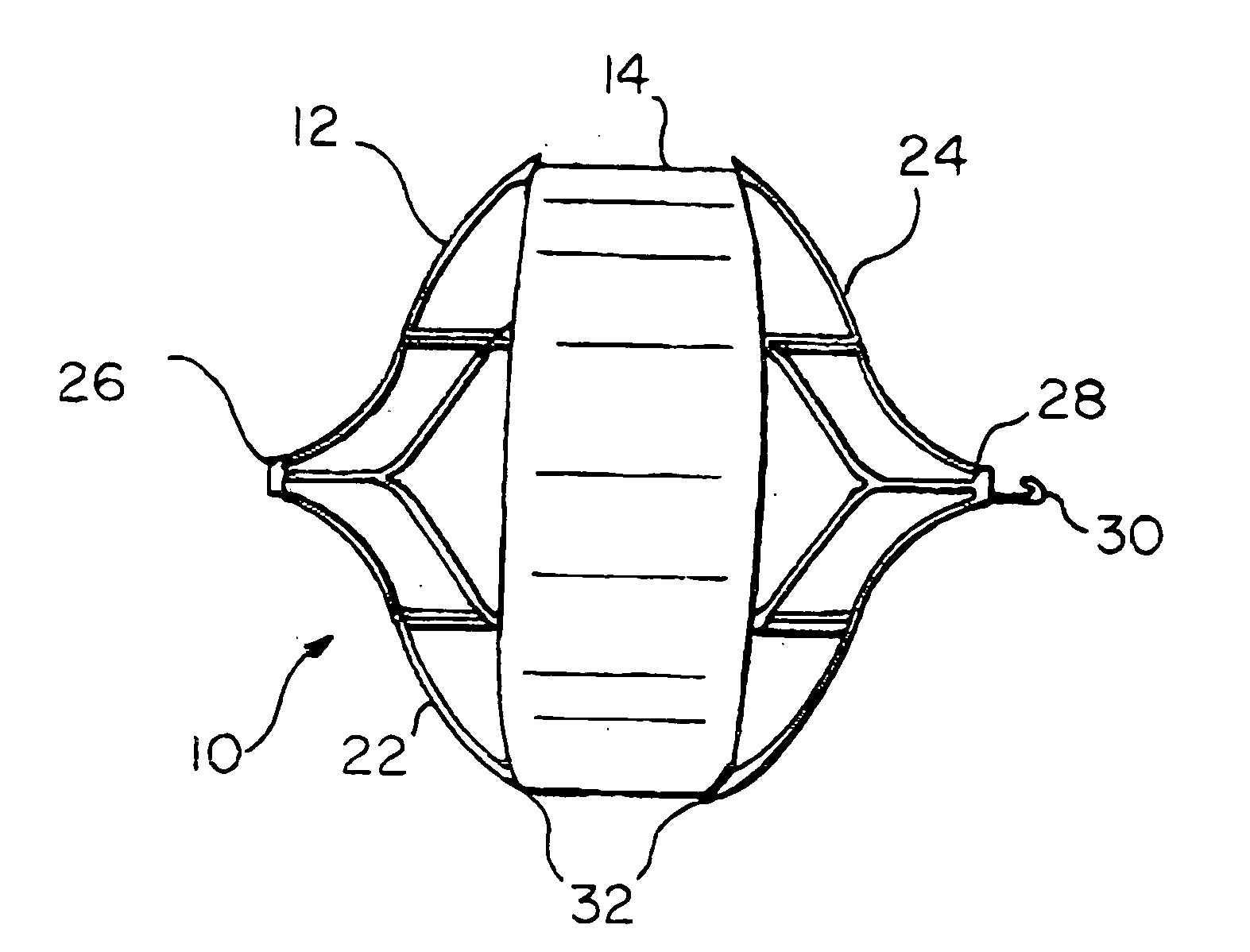
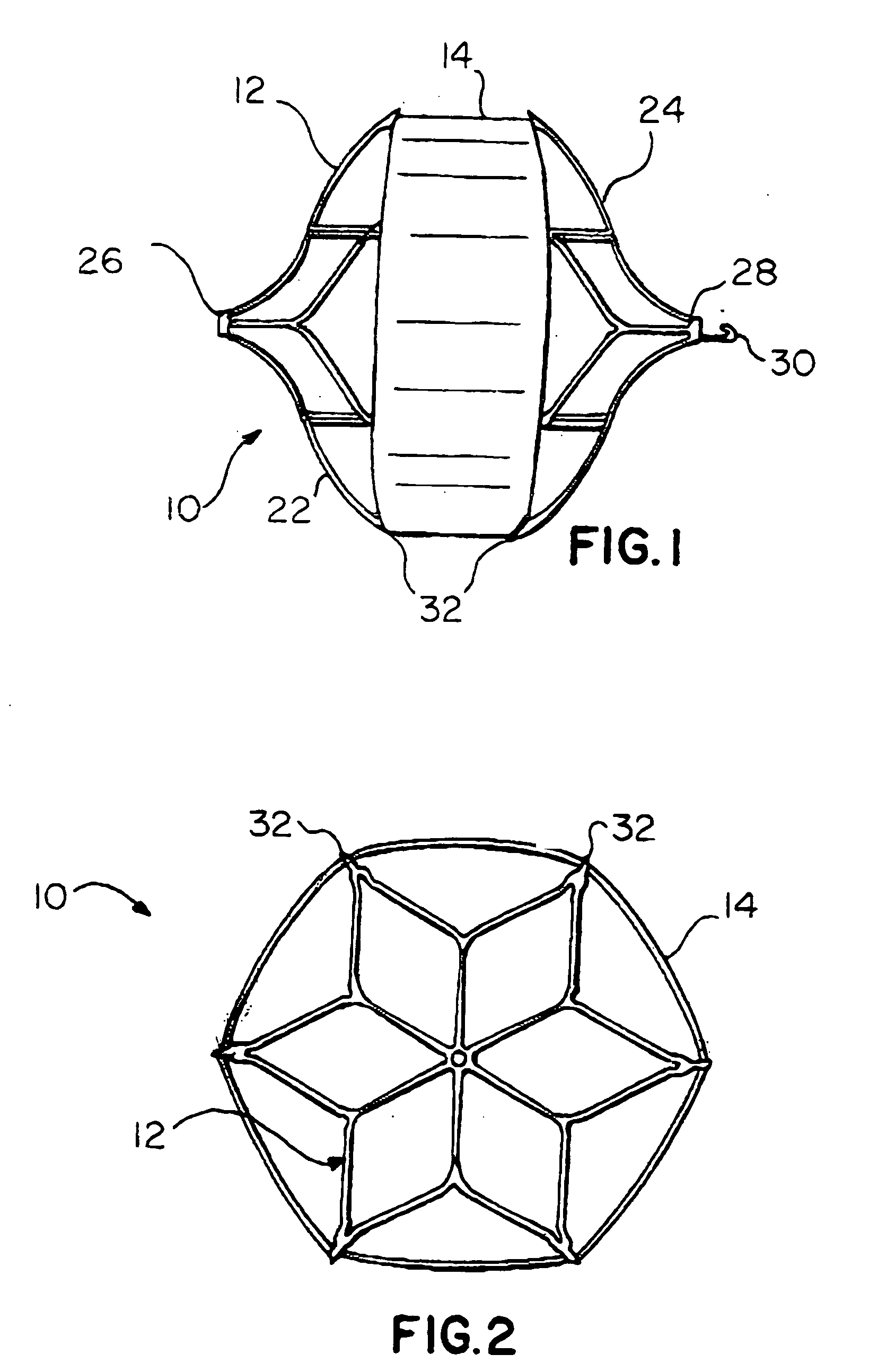
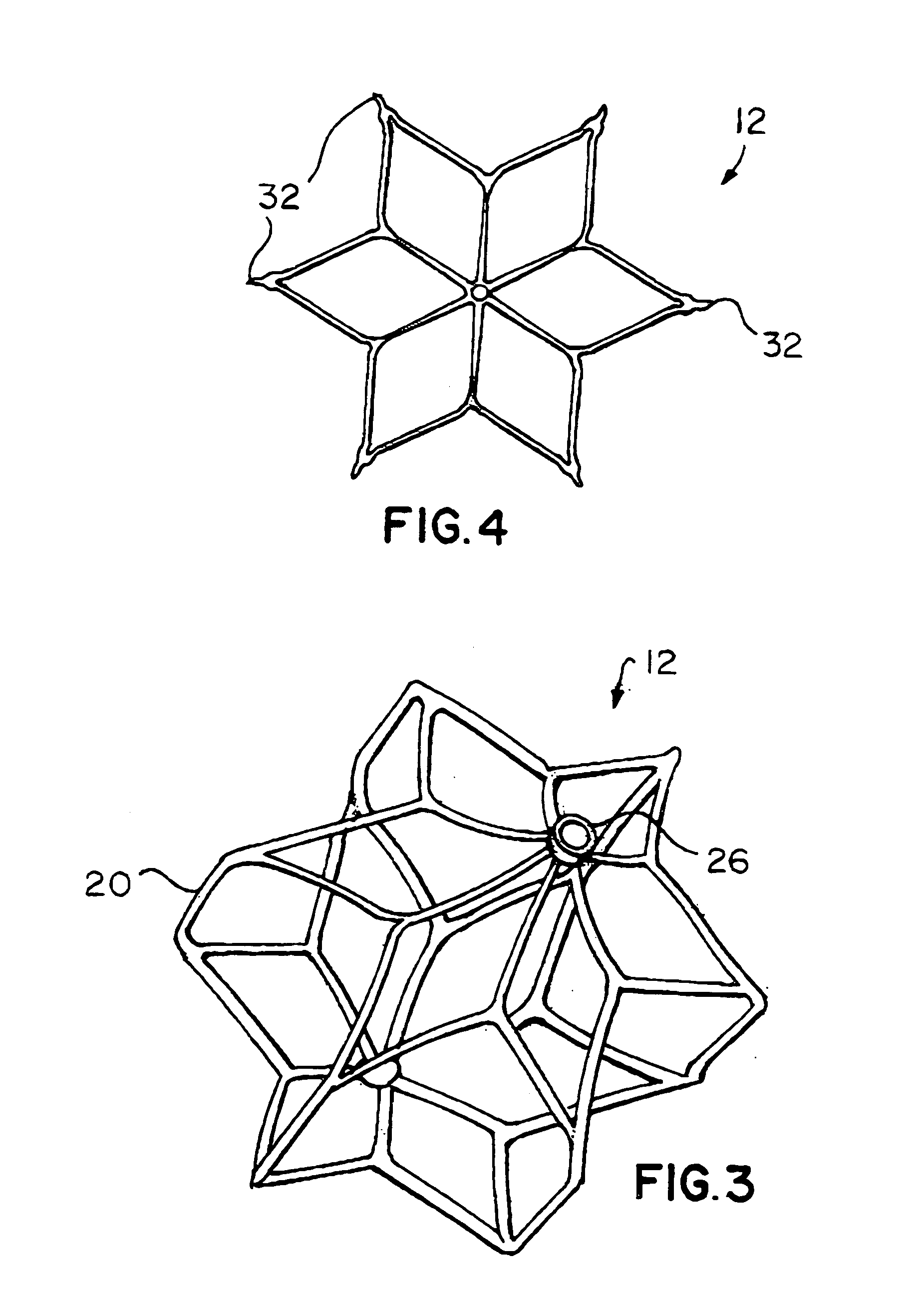
[0035] The drawings depict a vascular filter medical device 10 along the lines of the present invention. The drawings depict an example vascular filter medical device 10, which includes a filter structure 12 and a sleeve 14. Sleeve 14 is affixed to filter structure 12 in any suitable manner, including adhesives, stitching, or simply weaving sleeve 14 among the members of filter structure 12.

[0036] Medical device 10 has an expanded shape, shown in FIGS. 1 and 2, and an initial compressed shape, shown in FIG. 9. If medical device 10 is delivered with a catheter 16, and a pushing wire or mandrel 18, medical device 10 will have the initial compressed ...


PUM


Abstract

A covered vascular filter can be placed in a blood vessel, for the purpose of intercepting thrombus. The filter may be introduced to a desired site for medical treatment through a catheter which defines a lumen or passage and a distal port or opening. The filter tends to resiliently expand from a compressed shape when it is inside the catheter lumen, to an expanded shape when the filter is pushed from the catheter lumen. A cover or sleeve over those portions of the filter that would otherwise contact the vessel wall tends to reduce pressure on the vessel wall. The sleeve also tends to resist growth of the vessel wall among the elements of the filter, called endothelialization. In other words, the sleeve resists incorporation of the filter elements into the vessel wall, enabling the filter to be retrievable for a longer time. The various features of the present invention may be used singly or in any combination, as desired in a particular vascular filter.

Description

BACKGROUND AND SUMMARY OF THE INVENTION [0001] 1. Technical Background [0002] The present invention relates to a vascular filter with a sleeve covering, which can be temporarily or permanently placed inside a blood vessel for the purpose of intercepting thrombus. [0003] 2. Discussion [0004] Some basic types of vascular filters are generally known, wherein a single filter element, mesh or member extends across the direction of flow inside a blood vessel. Several features may be desirable for vascular filters, including non-surgical or “percutaneous” delivery of the filter to a desired site, and expansion from a preferably small initial size to an expanded working size that matches the vascular anatomy at the desired site. Also, a vascular filter should preferably capture a sufficient percentage of thrombus, while allowing blood to flow freely through the filter. [0005] Another desirable feature is a capability to remain reliably in the desired position in a patient's anatomy, referre...

Claims


Application Information

Patent Timeline
IPC IPC(8): A61M29/00
CPCA61F2/01A61F2002/011A61F2002/018A61F2230/0097A61F2230/005A61F2230/0067A61F2230/008A61F2002/016A61F2/0103A61F2/0108A61F2/011
Inventor BOSMA, GJALTHOOGEVEEN, YVONNE L.KOOM, MICHIELMULDER, RUDOLF T.
Owner CORDIS CORP
Why Eureka
Try Eureka