
Table with multiple configurations

a table and configuration technology, applied in the field of conference tables, can solve the problems of arranging furniture, unable to meet the needs of other purposes, and the table is not well-suited to other purposes, so as to facilitate viewing a speaker, convenient configuration to suit a number of different purposes, and efficient use for different purposes

Inactive Publication Date: 2006-03-02
MAGNA DESIGN
View PDF24 Cites 48 Cited by
  • Summary
  • Abstract
  • Description
  • Claims
  • Application Information

AI Technical Summary

Benefits of technology

[0009] Accordingly, one of the advantages of the present invention is that it provides a table that can readily be configured to suit a number of different uses or functions. As a result, a space such as a conference room that is equipped with such a table can be efficiently used for different purposes without having to exchange or move furniture around the room. For example, if a pair of separate but facing tables are needed, sections of the table, which are rotatably supported by a base, can be moved apart to present generally parallel, spaced-apart table sections, thereby avoiding the need to bring an additional table into the room. Alternatively, one or more table sections can be rotated relative to the base to present a “V” shape configuration of the table sections that is selectively open at either end of the table to enable people seated around the table to more easily view a speaker and / or another object of interest, such as a display screen or monitor, disposed at open end of the “V” shape configuration.
[0010] The table sections are supported by the base and preferably, at other points adjacent to their ends, by a plurality of table supports. Each table support engages only one of the table sections, so as to avoid interfering when one of the table sections is moved relative to another table section. The lower end of each of the table supports preferably includes a device for reducing friction, such as a sliding surface or a caster, to further facilitate movement of the table sections while at least partially supported by the table supports.
[0011] In addition, one embodiment of the present invention includes utility trays that extend along the undersurface of the table sections and which are configured to receive cables and leads that pass through the base of the table. Included within the utility trays are electrical power strips that are connected to a source of alternating current through leads that extend downwardly through the base. The cables and leads within the utility trays can be accessed at different points along the length of the table sections. As a result, even when table sections are moved, connections to the cables and leads disposed within the utility tray are available through an opening into the utility tray through the table surface. Persons seated around the table are thus provided ready access to integral data and electrical connections within the utility trays. To further enhance the appearance of the table surface system and hide the cables and leads that are conveyed to the utility trays, an extensible cover is joined to each of the table sections so that as the table sections are moved relative to one another, the extensible cover continuously covers the cables and leads that are conveyed through an opening at the top of the base.

Problems solved by technology

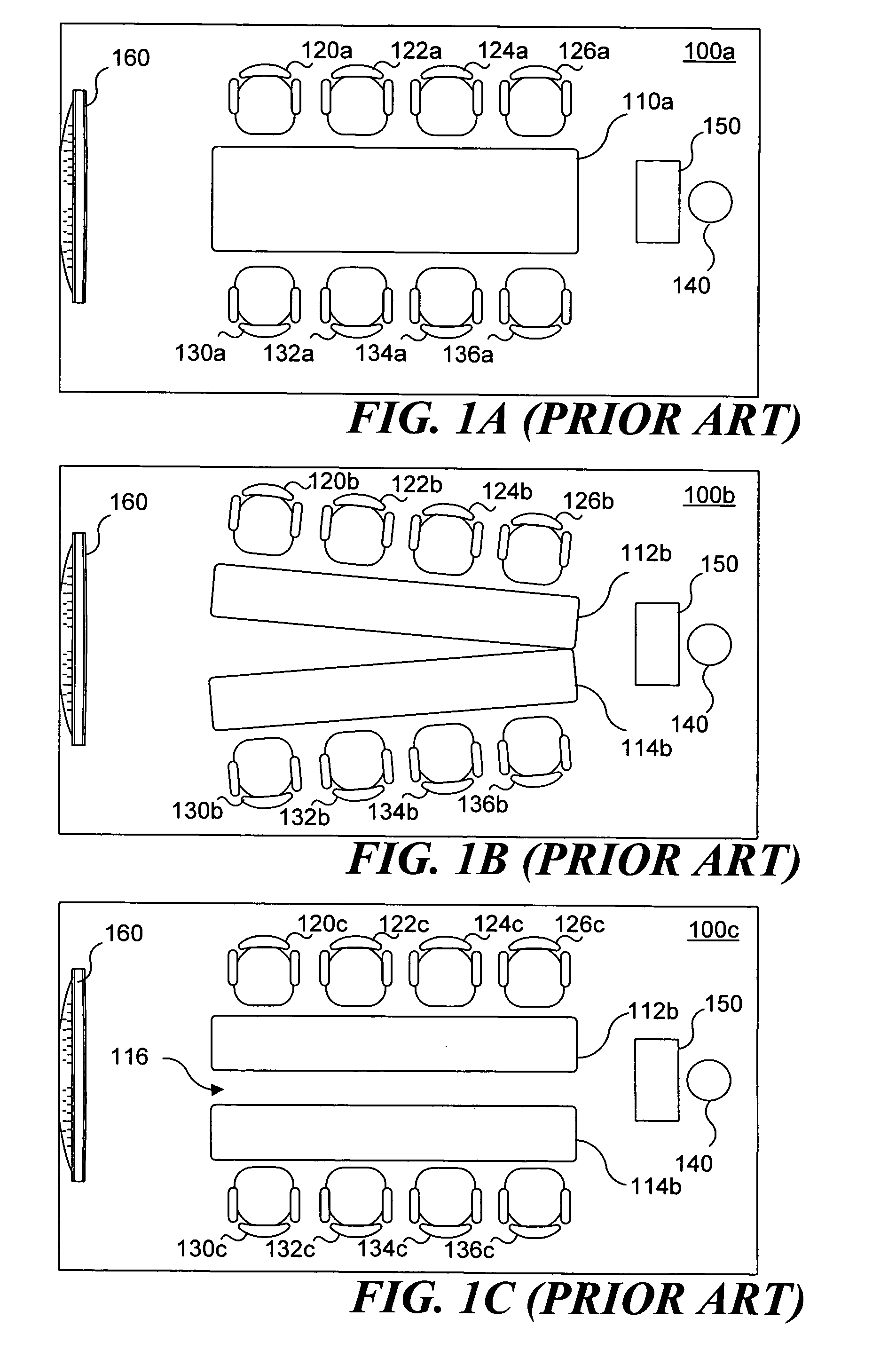
Unfortunately, conference room table 110a and chairs 120a-136a are less well-suited to other purposes.
This prior art solution to the problem of achieving multiple configurations to address different functions and needs for conference tables unfortunately also has drawbacks.
Unfortunately, arranging furniture as shown in FIG. 1C again may involve nontrivial labor in moving conference tables 112b and 114b.
Unfortunately, because one of the objects of using two separate tables 112b and 114b is to permit the reconfiguration of the conference tables to be readily carried out by moving the conference tables, it is not practical to equip these movable conference tables with cabling trays and conduits, since the data and power leads would then be exposed when the tables are moved to achieve the different configurations, creating a tripping hazard.
Considering the examples of FIGS. 1A-1C, having either one conventional conference room table or a plurality of narrower tables that can be moved to achieve different configurations is not a complete solution to the problem of addressing the need for different configurations discussed above.

Method used


Image

  • Table with multiple configurations
  • Table with multiple configurations
  • Table with multiple configurations

Examples


Embodiment Construction

Structure of Multipurpose Conference Room Table

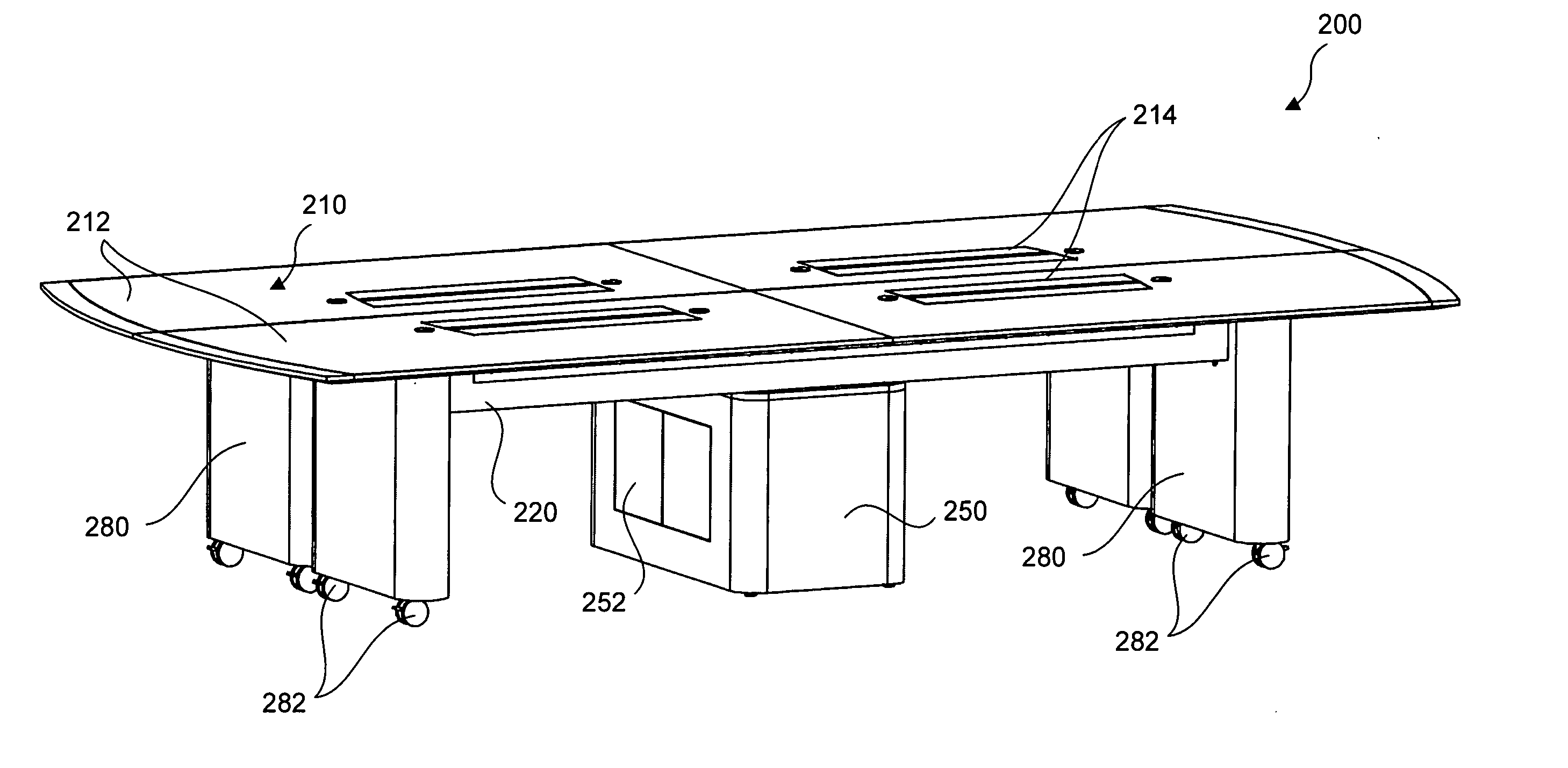
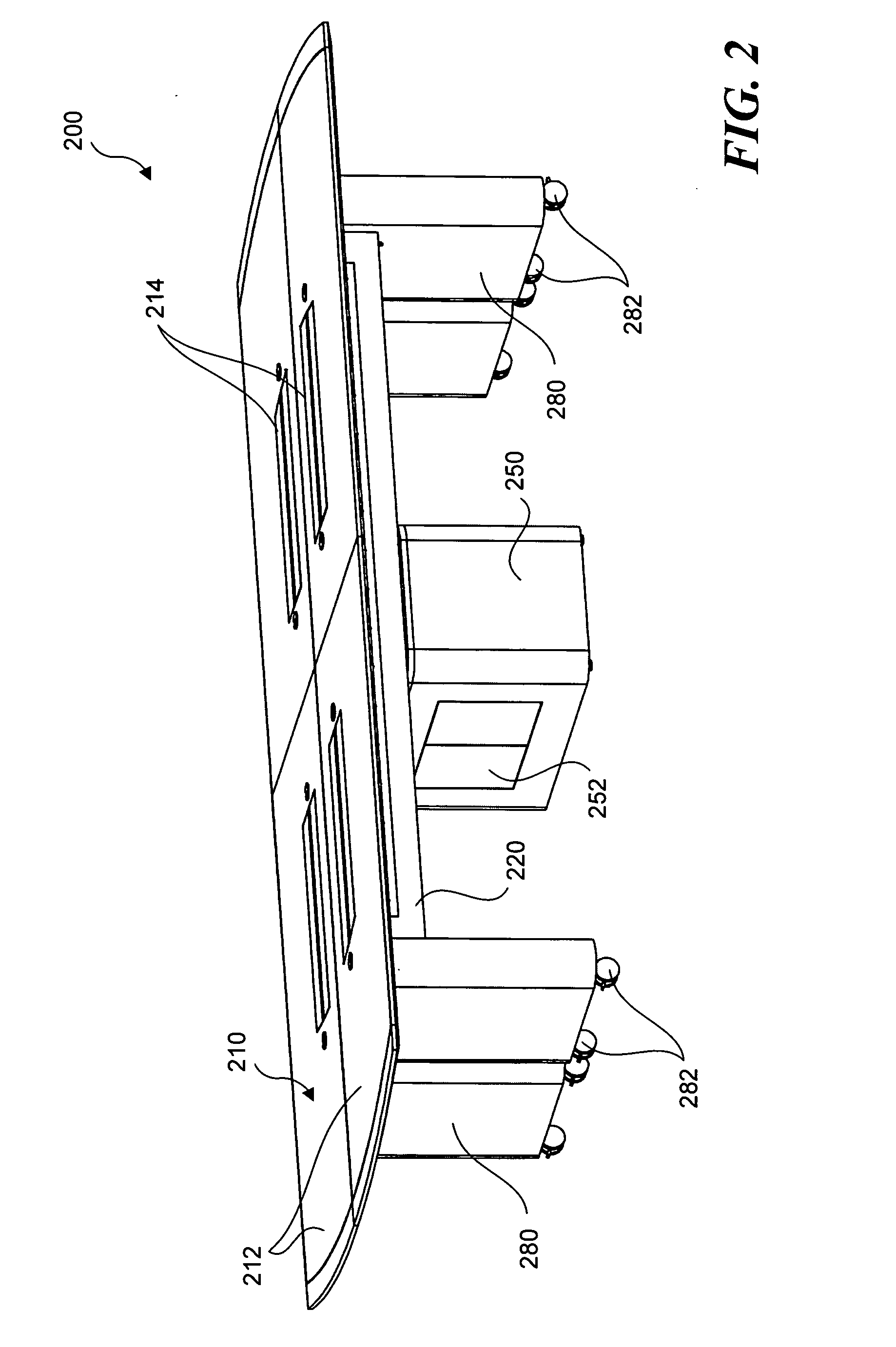
[0032]FIG. 2 is an isometric view of a table 200 in a retracted position, according to an embodiment of the present invention. FIG. 3 illustrates an exploded view of table 200, showing more detail of its internal structure. Table 200 includes a tabletop 210, which has a plurality of table surface sections 212, which are described below in further detail. Surface sections 212 include a plurality of closeable access openings 214, permitting access to an interior of utility trays 220 that are attached to the undersides of surface sections 212. The interior of utility trays 220 convey leads 236 for data, signals, and power. These leads provide network access, data communication, electrical power, and other functions for portable computers or other devices that one or more persons sitting at table 200 may be using.

[0033] Tabletop 210 is supported by a base 250 and a plurality of table supports or legs 280. Base 250 supports tabletop 210 a...


PUM


Abstract

A table includes a plurality of surface sections joined to a base. At least one of the surface sections is joined to the base with an attachment device having a slidable portion and a rotatable portion. A mounted end of the slidable portion is secured to the base and the opposite end of the slidable portion is slidably coupled to a rotatable joint, which is mounted to one of the surface sections. The rotatable joint is configured to rotate relative to the base, so that the surface section can be translated and rotated relative to the base to enable the table to readily be changed into four different configurations. Utility trays mounted under the surface sections provide access to power and data leads feeding from the base. A pleated accordion fold cover hides the attachment device and leads when a gap is formed between the surface sections.

Description

FIELD OF THE INVENTION [0001] The present invention generally pertains to conference tables, and more specifically, to conference tables that are selectively configurable in a plurality of different configurations. BACKGROUND OF THE INVENTION [0002] Most office suites include one or more conference rooms. These conference rooms may be used for any number of functions, but are typically used for meetings in which participants are seated around a table to discuss matters of interest to the participants. While a single conference table with seating on both sides can server this function, there are times when it is desirable to provide two sets of tables that are spaced apart from each other longitudinally. For example, it might be desirable to seat opposing parties along opposite sides of spaced-apart tables during negotiations. Still further, conference rooms might host presentations where a presenter, standing at one end of the table and using one or more visual aids, such as a video...

Claims


Application Information

Patent Timeline
IPC IPC(8): A47B37/00
CPCA47B1/08A47B2200/0079A47B21/06A47B1/10
Inventor STEVENS, JOHN R.GIOVANNONI, DONALD E.
Owner MAGNA DESIGN
Learn More