Steering control device

a control device and steering technology, applied in the direction of steering initiation, instruments, vessel construction, etc., can solve the problems of increasing the number of matching steps, difficult to freely set the hysteresis width and the slope of the steering reaction torque, and complicated computation processing, etc., to achieve natural steering feeling, suitable steering reaction torque, and improved steering feeling

Active Publication Date: 2006-03-02
MITSUBISHI ELECTRIC CORP
View PDF12 Cites 25 Cited by
  • Summary
  • Abstract
  • Description
  • Claims
  • Application Information

AI Technical Summary

Benefits of technology

[0011] The present invention has been made to solve the problems as described above, and has an object to provide a steering control apparatus in which a hysteresis width and a slope of a target steering reaction torque are respectively adjusted, so that a target steering reaction torque to improve a steering feeling can be easily obtained, and a suitable steering reaction torque can be obtained even if road surface friction is changed.
[0012] A steering control apparatus of the invention includes target steering reaction torque generation means for generating a target steering reaction torque as a target value of a steering reaction torque applied to a steering wheel, and performs a control so that the steering reaction torque is coincident with the target steering reaction torque, in which the target steering reaction torque ge

Problems solved by technology

Further, in the conventional steer-by-wire disclosed in JP-A-2002-274405, since the steering reaction torque is set from the relation of the assist map of the power steering and the estimated self-aligning torque, the steering feeling comparable to the vehicle equipped with the power steering system can be obtained, however, it is not easy to freely set the hysteresis width and the slope of the steering reaction torque so as to improve the steering feeling more than the vehicle equipped with the conventional power steering apparatus.
Besides, in the conventional steering control apparatus disclosed in JP-A-2002-19631, since it is necessary to previously set the relational expression

Method used


Image

  • Steering control device
  • Steering control device
  • Steering control device

Examples


embodiment 1

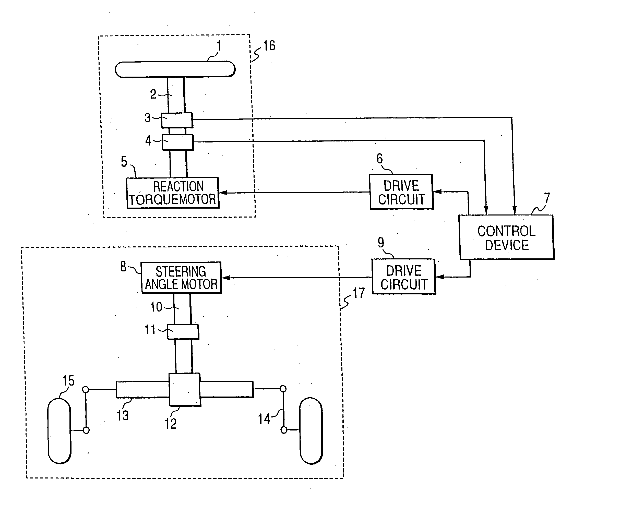
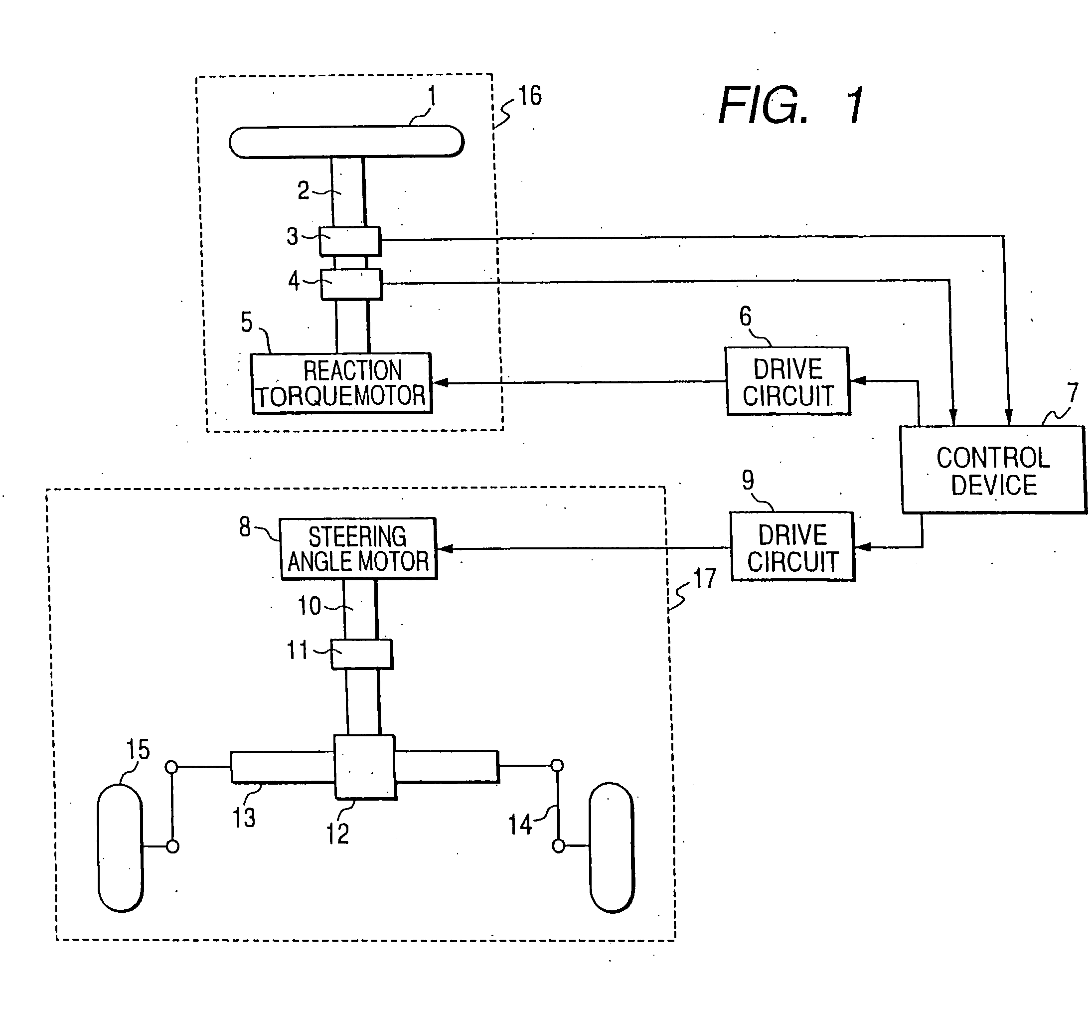
[0026]FIG. 1 is a view showing an outline of a structure of a steering control apparatus according to embodiment 1 of this invention.

[0027]FIG. 1 shows a so-called steer-by-wire system steering control apparatus in which a steering mechanism 16 by which a driver operates a steering wheel 1 is not mechanically coupled to a wheel turning mechanism 17 for turning a wheel 15. The steering mechanism 16 includes steering wheel angle detection means 3 for detecting a steering angle of the steering wheel 1 through a steering wheel shaft 2, steering reaction torque detection means 4 for detecting a steering reaction torque applied to the steering wheel, and a reaction torque motor 5 for arbitrarily controlling this steering reaction torque. The wheel turning mechanism 17 includes wheel steering angle detection means 11 for detecting an angle corresponding to a wheel steering angle of the steered wheel, and a steering angle motor 8 for arbitrarily controlling the wheel steering angle. A rota...

embodiment 2

[0071]FIG. 9 is a view showing an outline of a structure of a steering control apparatus according to embodiment 2 of this invention.

[0072] As compared with the steering control apparatus of FIG. 1 in which the steering mechanism 16 by which the driver operates the steering wheel 1 is not mechanically coupled to the wheel turning mechanism 17 which rotates the wheel 15, in FIG. 9, a steering mechanism 16 and a wheel turning mechanism 17 for turning a wheel 15 are mechanically coupled to each other through a planetary gear mechanism 18 and a planetary gear mechanism 19.

[0073] A steering wheel shaft 2 is coupled to a carrier 21 of the planetary gear mechanism 18. A reaction torque motor 5 is connected to a ring gear 22 of the planetary gear mechanism 18 through a gear, and controls the rotation of the ring gear. A steering shaft 10 is coupled to a carrier 25 of the planetary gear mechanism 19. A sun gear 20 of the planetary gear mechanism 18 and a sun gear 24 of the planetary gear m...

embodiment 3

[0088]FIG. 10 is a structural view showing an outline of a structure of a steering apparatus according to embodiment 3 of this invention. In the steering apparatus in which when a driver operates a steering wheel 1, a rotation angle of the steering wheel 1 is converted into a wheel steering angle of a wheel 15 through a steering shaft 10, a pinion gear 12, a rack 13, and a knuckle arm 14, the electric power steering control apparatus calculates a motor current target value of an assist motor 29 by a control device 7 on the basis of the output of steering reaction torque detection means 4 for detecting a steering reaction torque in the case where the driver steers. A drive circuit 30 controls a drive current so that the target current set by the control device 7 is applied to the assist motor current.

[0089] In a conventional electric power steering control apparatus, an assist torque is set on the basis of the output of the steering reaction torque detection means 4, and the motor c...


PUM


Abstract

In an electrical power steering apparatus, steering shaft reaction torque is estimated by a steering shaft reaction torque estimation unit, and a reference road reaction torque is estimated by a reference road reaction torque estimation unit. The estimated steering shaft reaction torque and the reference road reaction torque are weighted, and in response, a target steering reaction torque is set by a target steering reaction torque generation unit, hysteresis width and slope of the target steering reaction torque are respectively adjusted, and steering feeling is thereby easily improved.

Description

TECHNICAL FIELD [0001] The present invention relates to a steering control apparatus in which the hysteresis width and slope of a target steering reaction torque are adjusted to improve a steering feeling. BACKGROUND ART [0002] In a conventional steering control apparatus disclosed in JP-A-2000-238654, a steering reaction torque is determined by the following.steering reaction torque=K·tire reaction torque+correction value Where, the correction value is set from a vehicle speed and a steering angle. [0003] By this, a steering reaction torque characteristic (steering angle—steering reaction torque characteristic) with a suitable hysteresis is realized. [0004] Besides, in a convention steering control apparatus disclosed in JP-A-2002-274405, a steering reaction torque is determined by the following. By that, in a separate type power steering apparatus in which mechanical coupling is not performed, a steering feeling comparable to that of a vehicle equipped with a conventional power st...

Claims


Application Information

Patent Timeline
IPC IPC(8): B62D7/15B62D6/00
CPCB62D6/008B62D6/006B62D6/02B62D5/0463
Inventor ENDO, MASAYAKURISHIGE, MASAHIKOSATAKE, TOSHIHIDEINOUE, NORIYUKI
Owner MITSUBISHI ELECTRIC CORP
Why Eureka
Try Eureka