
Discharge member and container provided with the same

Inactive Publication Date: 2006-03-02
OTSUKA PHARM CO LTD +1
View PDF10 Cites 21 Cited by
  • Summary
  • Abstract
  • Description
  • Claims
  • Application Information

AI Technical Summary

Benefits of technology

[0008] With this background, an object of the present invention is to provide a delivery device to be fitted at the mouth of a container so as to deliver a liquid contained therein in the form of drops, that enables it to prevent the liquid from flowing backward and achieve aseptic entry of air into the container after delivering the liquid.
[0009] Another object of the present invention is to provide a container that allows it to eliminate or reduce the use of an antiseptic for the purpose of preventing the content liquid from being degenerated or deteriorated, and achieves smooth delivery of the liquid without clogging the outlet opening even when the content liquid is a suspension.

Problems solved by technology

However, there are such problems that it is difficult to prescribe a composition that includes an antiseptic depending on the type of ophthalmic solution, and the antiseptic may cause a side effect such as allergy in the user of the ophthalmic solution.
Although this eyedropper can eliminate the use of aseptic agent, high cost limits the applications thereof and prohibits wider applications.
However, it is necessary to provide an inner container that is constituted from the inner layer and is easily deformed, so as to accommodate a change in the inside pressure of the container due to the delivery of the liquid, resulting in a high manufacturing cost of the container.
In this case, however, when the porous filter dries up after being wetted by the liquid, there is a possibility of the filter being loaded with the solute contained in the liquid.

Method used


Image

  • Discharge member and container provided with the same
  • Discharge member and container provided with the same
  • Discharge member and container provided with the same

Examples


Embodiment Construction

[0063] The delivery device of the present invention and the container provided therewith will now be described in detail below with reference to accompanying drawings.

[0064] [First Delivery Device and Container]

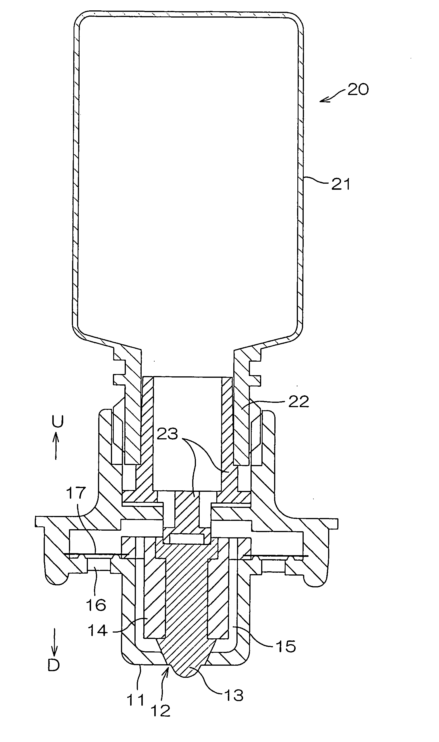
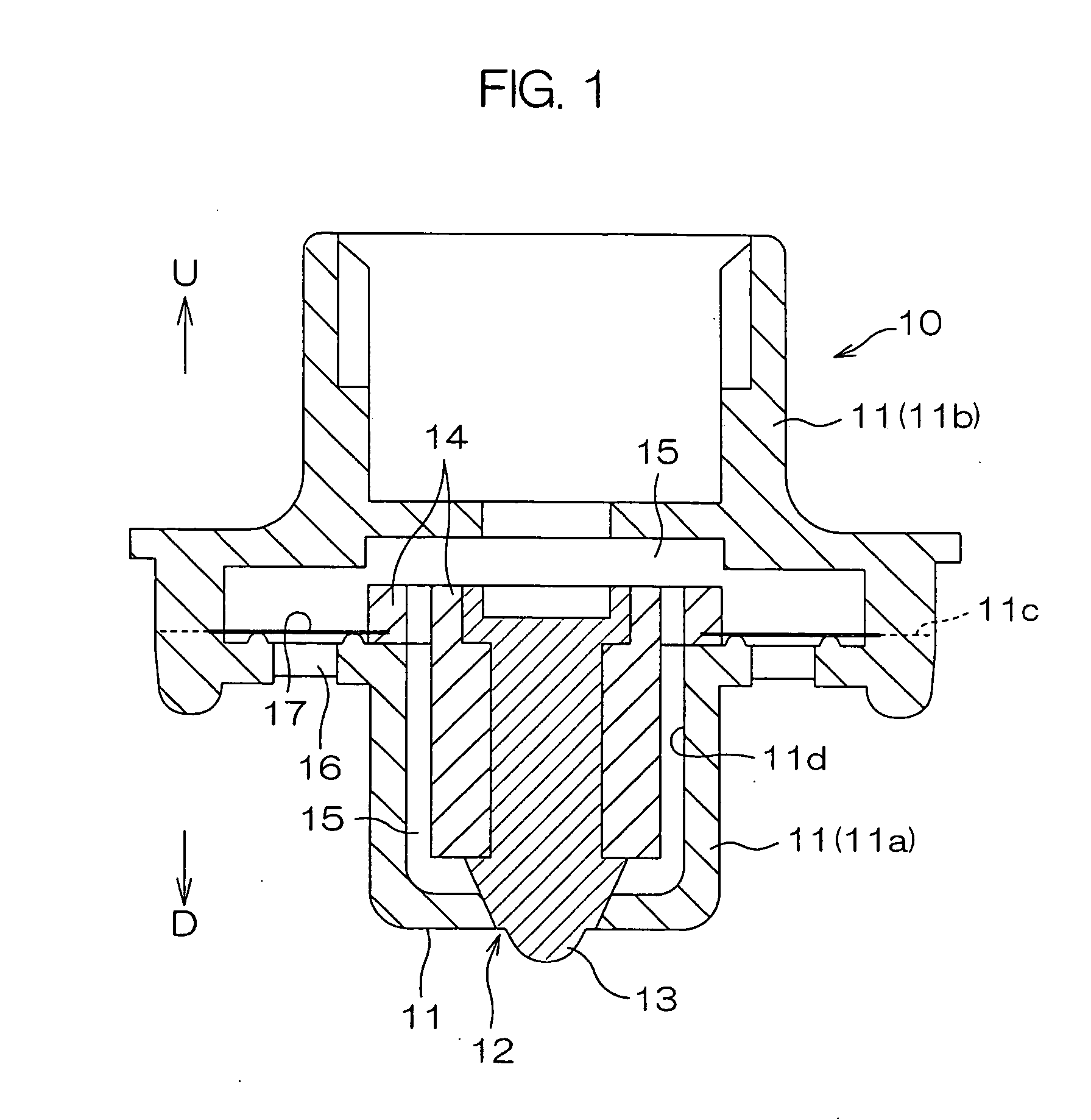
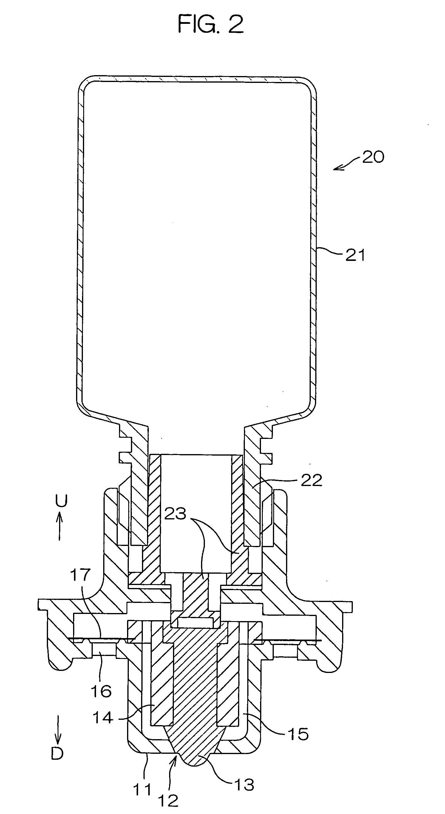
[0065] First delivery device 10 according to the present invention comprises an outlet portion 11 having substantially bottomed tubular shape (or substantially bowl like shape) that has an outlet orifice 12 at the bottom thereof, a valve element 13 disposed in the outlet portion 11 that, when there is no liquid pressure exerted thereon from the upstream side U, closes the outlet orifice 12 and, when forced by the liquid pressure from the upstream side U, undergoes compressive deformation and opens the outlet orifice 12, a locking member 14 that is disposed in the outlet portion 11 so as to define a flow passage 15 between itself and an inner surface 11d of the outlet portion and fastens the valve element 13 in the upstream side U, and a vent hole 16 that communicates with th...


PUM


Abstract

The present invention provides a delivery device that delivers a liquid contained in a flexible container when the container is depressed, and the container that has the delivery device attached to the mouth thereof. The delivery device comprises an outlet portion having substantially bottomed tubular shape or substantially bowl like shape that has an outlet orifice at the bottom thereof, a valve element made of an elastic material that, when there is no liquid pressure exerting thereon, closes the outlet orifice and / or a flow passage that communicates with the outlet orifice in the outlet portion and, when a liquid pressure is exerted thereon, deforms so as to open the outlet orifice and / or the flow passage, and a vent hole that communicates with the outlet orifice and the flow passage via an air filter, wherein deformation of the valve element is achieved by a liquid pressure lower than the pressure required to pass the liquid through the air filter, and opening of the outlet orifice and / or the flow passage cannot be achieved by the pressure required to pass air through the air filter from outside.

Description

TECHNICAL FIELD [0001] The present invention relates to a delivery device that delivers a liquid contained in a flexible container when the container is depressed, and the container provided with the delivery device. BACKGROUND ART [0002] A container used to drip a liquid contained therein such as eye dropper employs a delivery device 150 such as one shown in FIG. 41(a), (b). The delivery device 150 is fitted at a mouth 152a of a container body 152, having an outlet orifice 151 of which inner diameter is set so as to allow it to deliver the liquid by depressing the container body 152 and keep the liquid from being delivered when the container body 152 is not depressed, and an outlet opening 153 of which a dimension is set so as to hold the liquid in the form of a drop 154. [0003] The container as shown in FIG. 41 has a high possibility of the outlet opening 153 being contaminated by microorganisms such as bacteria and dust. In the case of an eye dropper, in particular, it is very li...

Claims


Application Information

Patent Timeline
IPC IPC(8): B65D37/00A61J1/20B65D47/20B65D51/16
CPCB65D47/20B65D47/2018B65D51/1616B65D47/2075B65D47/2068B65D47/18B65D51/16A61J1/05
Inventor KAWASHIRO, YASUSHISUGAHARA, YUJI
Owner OTSUKA PHARM CO LTD
Learn More