
Mini card reader systems and methods

a card reader and card reader technology, applied in the field of card reader systems, can solve problems such as possible processing delays

Active Publication Date: 2006-03-02
FIRST DATA
View PDF4 Cites 14 Cited by
  • Summary
  • Abstract
  • Description
  • Claims
  • Application Information

AI Technical Summary

Benefits of technology

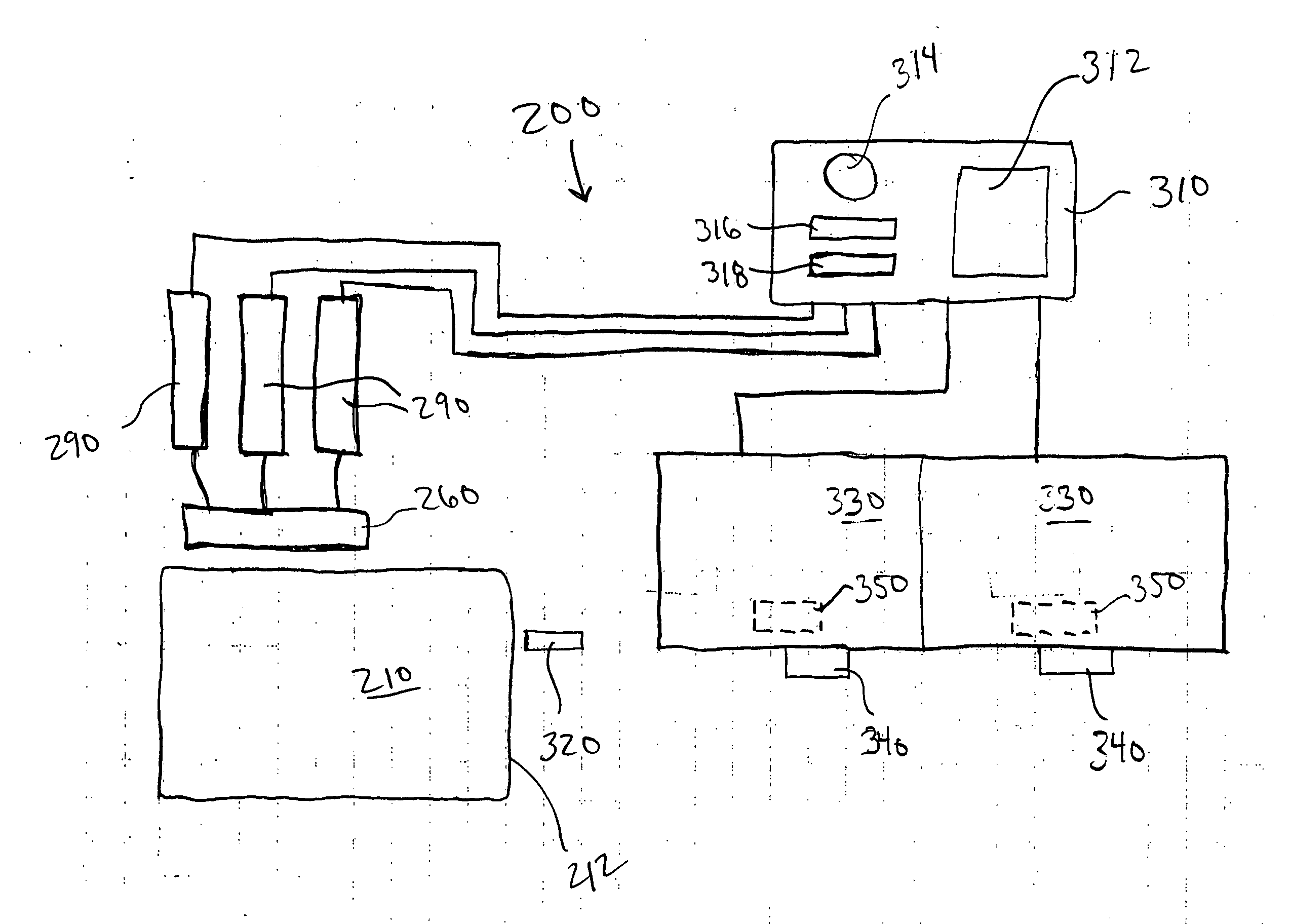
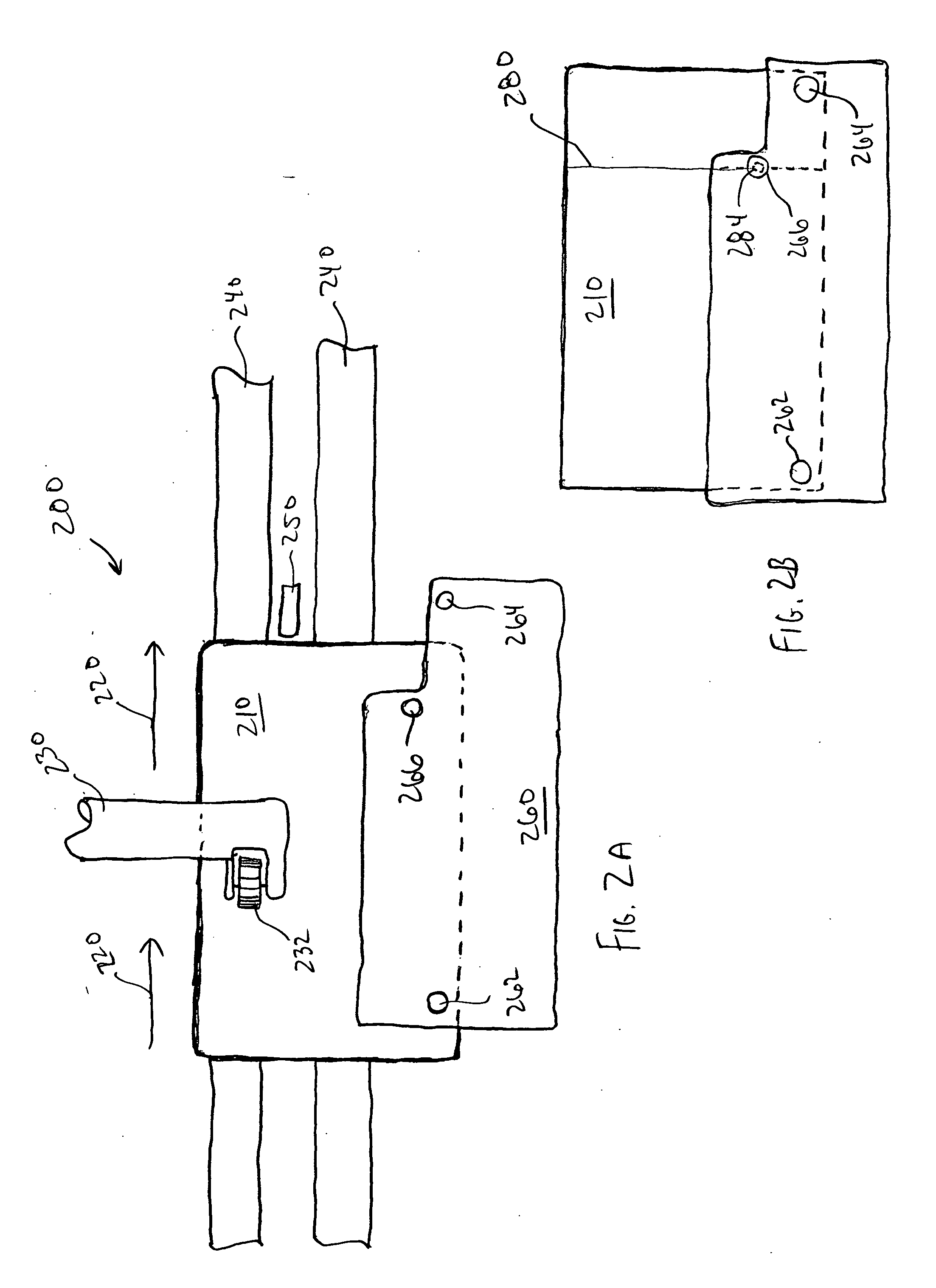
[0006] In one embodiment, a card reader system according to the present invention includes a means for sensing the presence of a scoring of a card at a specified card location. The system includes a read head adapted to read a magnetic stripe (magstripe) disposed on the card, and a circuit coupled to both the means for sensing and the read head. The circuit is adapted to receive input from the sensing means, to determine whether the card is a first size or a second size based on the received input, and to enable the read head to read the entire magstripe when the card is the first size and to read a portion of the magstripe when the card is the second size. In this manner, by providing an improved sensing device with card reader systems, the operation of the read head is controlled so that it is not fooled into believing more cards exist than are truly passing by the read heads. In one embodiment, the first card size is a CR80 card. In other aspects, the second card size is smaller than a CR80 card. Further, the second card size may be a scored CR80 card. The miniature card or smaller card may be created from the scored CR80 card.

Problems solved by technology

Unfortunately, when the card reader system reads the magnetic stripe on the back of a scored card, on some occasions the system read head detects the score.
As a result, the card reader falsely determines that the cards will not be matched with the appropriate customer card carrier, or the like, and an error is flagged.
Hence, considerable processing delays may occur as a result of the false reads caused by the miniature cards.

Method used


Image

  • Mini card reader systems and methods
  • Mini card reader systems and methods
  • Mini card reader systems and methods

Examples


Embodiment Construction

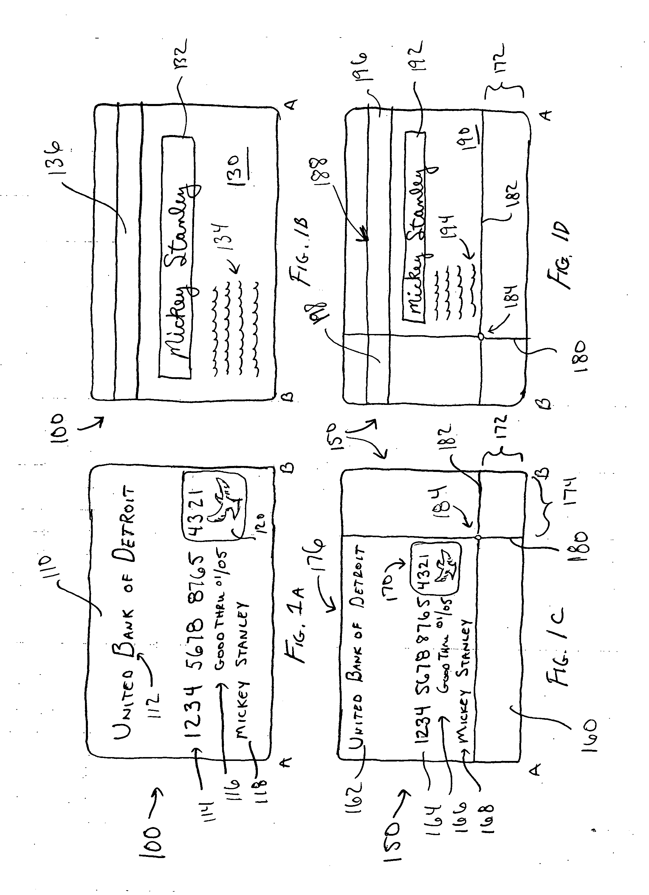
[0019]FIGS. 1A and 1B depict a presentation instrument 100 which may be processed through systems of the present invention. In one embodiment, presentation instrument 100 is a CR80 card, or a similar sized card. As noted, in one embodiment card 100 is a CR80 card that is about 85.6 mm in length by about 53.98 mm in height. Card 100 may be a credit card, debit card, Automated Teller Machine (ATM) card, telephone card, stored value card, and a wide range of other transaction-based cards. Card 100 has a first or front surface 110 and a second or back surface 130. First surface 110 may include a name of a bank 112, an account number 114, an expiration date 116, and a customer name 118, among other things. First surface 110 also may have one or more holographic images 120 disposed thereon for, among other things, security protection. Second or back surface 130 includes a signature block 132 for the customer to sign their name. Second surface 130 may further include written or printed tex...


PUM


Abstract

Improved card reader systems and methods are provided which are capable of processing miniature cards as well as larger cards. In one embodiment, the card reader system includes a means for sensing the presence of a scoring of a card at a specified card location. The system includes a read head adapted to read a magnetic stripe disposed on the card, and a circuit coupled to both the sensing means and the read head. The circuit is adapted to receive input from the sensing means, to determine whether the card is a first size or a second size based on the received input, and to enable the read head to read the entire magstripe when the card is the first size and to read a portion of the magstripe when the card is the second size. In this manner, by providing an improved sensing device with card reader systems, the operation of the read head may be controlled so that it is not fooled into believing more cards exist than are truly passing by the read heads. The first card size may be a CR80 card, and the second card size may be a scored CR80 card containing a mini card.

Description

BACKGROUND OF THE INVENTION [0001] The present invention is directed generally to card reader systems, and more specifically, to systems and methods for reading cards including miniature cards smaller than standard credit cards. [0002] Card readers currently exist that process credit cards by reading information contained on a magnetic stripe attached to the back of the card. One such system is the BOWE 7710 system, produced by BOWE Systec, having its headquarters in Augsburg, Germany. This system often is coupled with additional devices that allow new credit cards to be organized and attached to mailing inserts. The cards are then mailed to current or potential customers. Cards to date, including credit cards, automated teller machine (ATM) cards, debit cards, and the like, have generally conformed to a standard size referred to as a CR80 card. These CR80 cards are typically about eighty-five millimeters (85 mm) long and about fifty-four millimeters (54 mm) wide. [0003] Recently, s...

Claims


Application Information

Patent Timeline
Patent Type & Authority Applications(United States)
IPC IPC(8): G06K7/06
CPCG06K7/087
Inventor ISON, ERICCAILLIER, ROBERT L.
Owner FIRST DATA
Learn More