Organic light emitting display and display unit thereof

a technology of light-emitting display and display unit, which is applied in the field of organic light-emitting display and a display unit thereof, can solve the problem of high cost of such a technology

Active Publication Date: 2006-03-02
AU OPTRONICS CORP
View PDF2 Cites 35 Cited by
  • Summary
  • Abstract
  • Description
  • Claims
  • Application Information

AI Technical Summary

Problems solved by technology

In addition, the voltage drop of the main voltage line further causes another problem, the loading effect. FIG. 3 is a schematic illustration showing a conventional organic light emitting display, which displays a full white frame and a frame with an upper half of a black section and a lower half of a white section.
This approach, however, is uneconomic and the cost thereof is high.

Method used


Image

  • Organic light emitting display and display unit thereof
  • Organic light emitting display and display unit thereof
  • Organic light emitting display and display unit thereof

Examples


Embodiment Construction

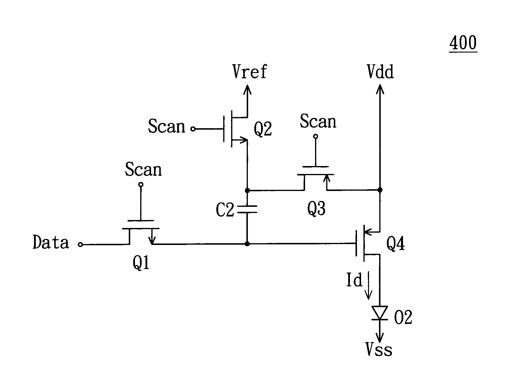
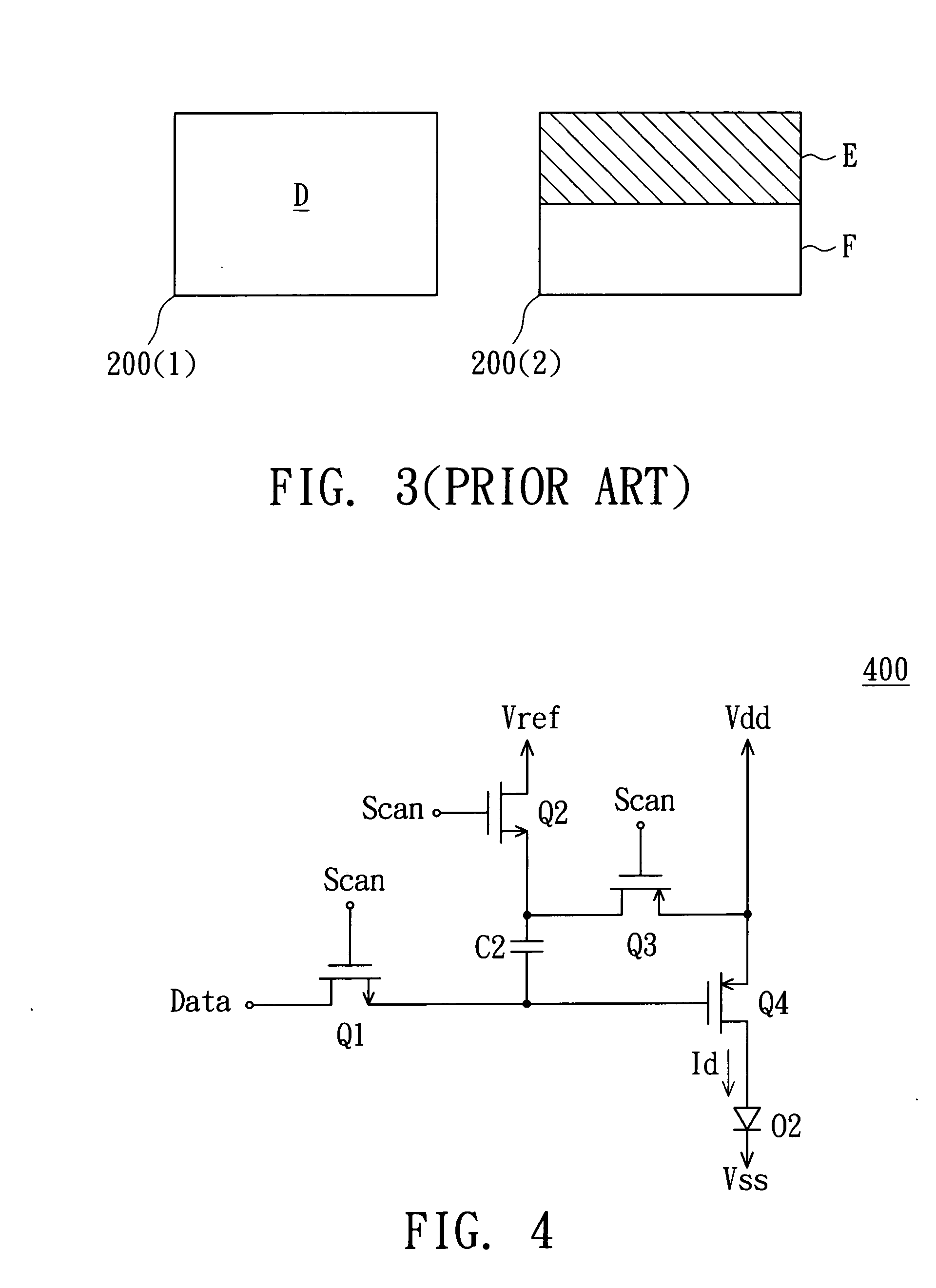
[0018]FIG. 4 is a circuit diagram showing an organic light emitting display unit according to a preferred embodiment of the invention. Referring to FIG. 4, the organic light emitting display unit 400 includes a PMOS transistor Q4, an OLED O2, a capacitor C2, a first switch Q1, a second switch O2 and a third switch Q3. The PMOS transistor Q4 generates a driving current Id and has a source coupled to the third switch Q3 and a drain coupled to a positive end of the OLED O2. The OLED O2 emits light according to the driving current Id and has a negative end coupled to a low main voltage Vss. The capacitor C2 has a first end coupled to the first switch Q1 and a gate of the PMOS transistor Q4, and a second end coupled to the second switch Q2. The third switch Q3 is coupled between the capacitor C2 and the PMOS transistor Q4. For example, the third switch Q3 connects the second end of the capacitor C2 to the source of the PMOS transistor O4.

[0019] The first switch Q1 is controlled by a sca...


PUM


Abstract

An organic light emitting display includes a display unit, a scan line, a data line, a reference line and a main voltage line. The display unit includes a first PMOS transistor, an OLED and a capacitor. The first PMOS transistor generates a driving current. The OLED emits light according to the driving current. The capacitor has a first end and a second end, and the first end and the second end selectively and respectively receives a data signal and a reference voltage according to a control signal. The scan line is for transmitting a scan signal. The data line is for transmitting the data signal. The reference line is for outputting the reference voltage. The main voltage line is for outputting a main voltage to the first PMOS transistor.

Description

[0001] This application claims the benefit of Taiwan application Serial No. 93126437, filed Sep. 1, 2004, the subject matter of which is incorporated herein by reference. BACKGROUND OF THE INVENTION [0002] 1. Field of the Invention [0003] The invention relates in general to an organic light emitting display, and more particularly to an organic light emitting display and a display unit thereof. [0004] 2. Description of the Related Art [0005]FIG. 1 is a circuit diagram showing a conventional organic light emitting display unit. Referring to FIG. 1, the organic light emitting display unit 100 includes a NMOS transistor T1, a PMOS transistor T2, a capacitor C1 and an OLED (Organic Light Emitting Diode) 01. The NMOS transistor T1 has a drain for receiving a data signal Data and a gate for receiving a scan signal Scan. The capacitor C1 has a first end coupled to a source of the NMOS transistor T1, and a second end for receiving a main voltage Vdd. The PMOS transistor T2 has a source coupl...

Claims


Application Information

Patent Timeline
Patent Type & Authority Applications(United States)
IPC IPC(8): G09G3/32
CPCG09G3/3233G09G2320/0233G09G2300/0842
Inventor LEE, KUO-SHENGHU, SHUO-HSIU
Owner AU OPTRONICS CORP
Why Eureka
Try Eureka