Memory system and method using ECC to achieve low power refresh

a memory system and memory technology, applied in the direction of digital storage, redundant data error correction, instruments, etc., can solve the problems of increasing the power consumption of a dram device with both the capacity and the operating speed, and the limited use of portable electronic devices such as notebook computers

Active Publication Date: 2006-03-02
MICRON TECH INC
View PDF99 Cites 86 Cited by
  • Summary
  • Abstract
  • Description
  • Claims
  • Application Information

AI Technical Summary

Problems solved by technology

The usefulness of portable electronic devices, such as notebook computers, is limited by the limited length of time batteries are capable of powering the device before needing to be recharged.
For example, electronic devices such a notebook computers, typically include dynamic random access memory (“DRAM”) devices that consume a substantial amount of power.
In general, the power consumed by a DRAM device increases with both the capacity and the operating speed of the DRAM devices.
The power consumed by DRAM devices is also affected by their operating mode.
A DRAM device for example, will generally consume a relatively large amount of power when the memory cells of the DRAM device are being refreshed.
A relatively large amount of power is consumed when refreshing a DRAM because rows of memory cells in a memory cell array are being actuated in the rapid sequence.
As a result, DRAM refreshes tends to be particularly power-hungry operations.
Further, since refreshing memory cells must be accomplished even when the DRAM is not being used and is thus inactive, the amount of power consumed by refresh is a critical determinant of the amount of power consumed by the DRAM over an extended period.
However, reducing the refresh rate increases the risk that data stored in the DRAM memory cells will be lost.
More specifically, since, as mentioned above, DRAM memory cells are essentially capacitors, charge inherently leaks from the memory cell capacitors, which can change the value of a data bit stored in the memory cell over time.
However, current leaks from capacitors at varying rates.
Some capacitors are essentially short-circuited and are thus incapable of storing charge indicative of a data bit.
On the other hand, current leaks from most DRAM memory cells at much slower rates that span a wide range.

Method used


Image

  • Memory system and method using ECC to achieve low power refresh
  • Memory system and method using ECC to achieve low power refresh
  • Memory system and method using ECC to achieve low power refresh

Examples


Embodiment Construction

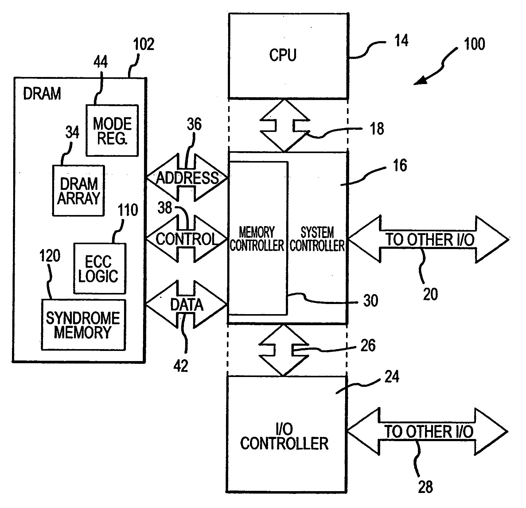
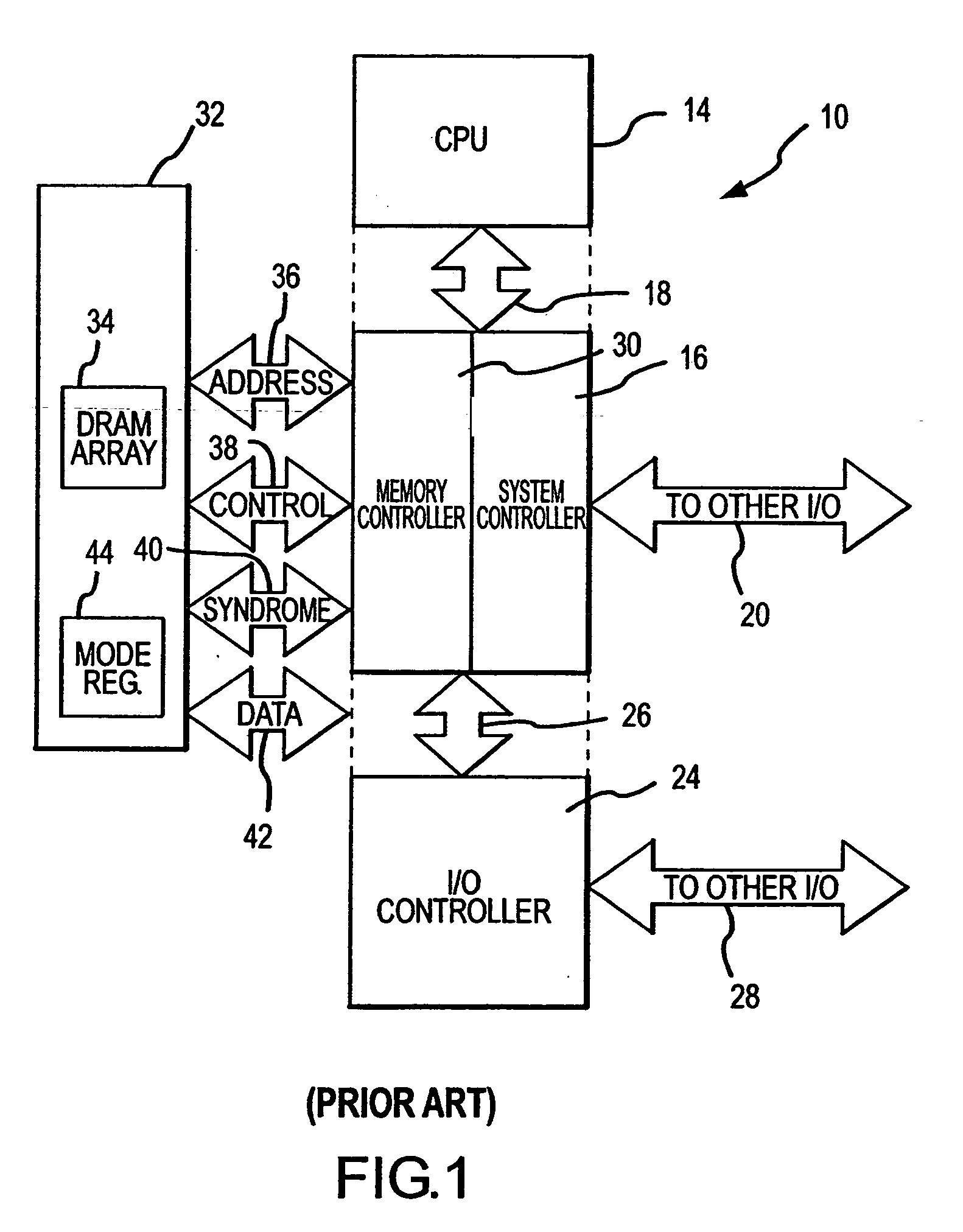
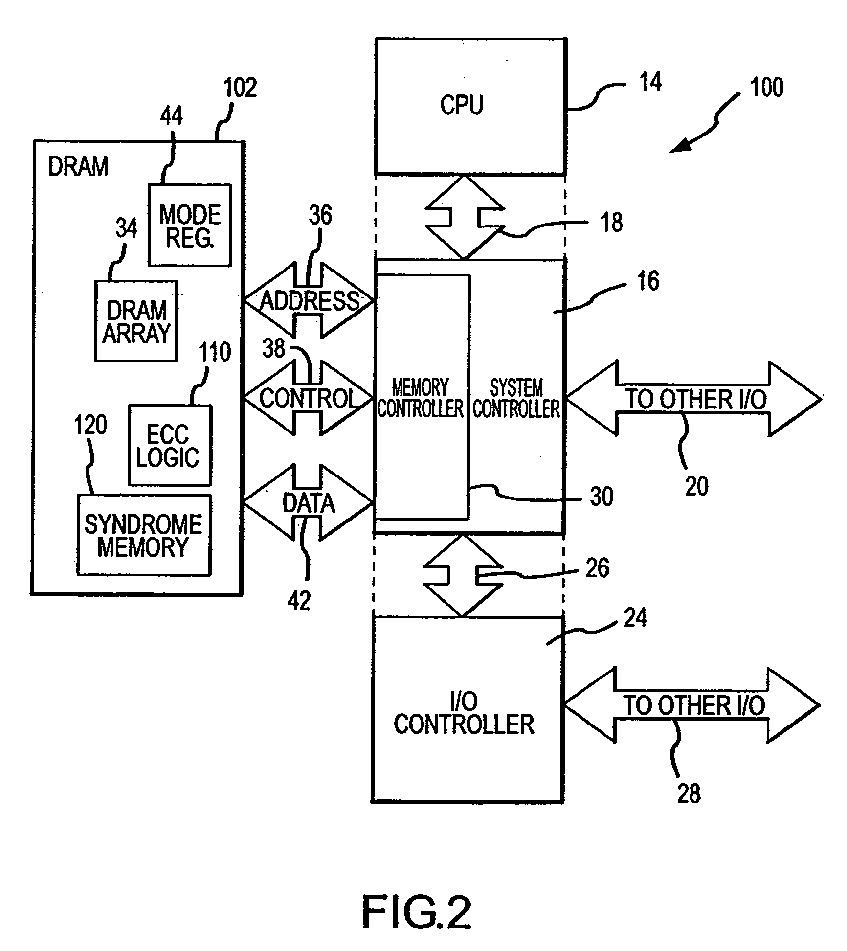
[0018] A computer system 100 according to one embodiment of the invention is shown in FIG. 2. The computer system 100 uses many of the same components that are used in the conventional computer system 10 of FIG. 1. Therefore, in the interest of brevity, these components have been provided with the same reference numerals, and an explanation of their operation will not be repeated. The computer system 100 of FIG. 2 differs from the computer system 10 of FIG. 1 by including a DRAM 102 that includes a syndrome memory 120 and ECC logic 110, and by omitting a syndrome bus. As explained in greater detail below, prior to entering a reduced power refresh mode, the ECC logic 110 generates a syndrome from data stored in the DRAM array 34 and then stores the syndrome in the syndrome memory 120. The ECC logic 110 uses the stored syndromes to check and then correct data read from the DRAM array 34 during low power refresh, which occurs at a rate that is sufficiently low that data retention error...


PUM


Abstract

Rows of DRAM memory cells are refreshed at either a relatively high rate during normal operation or a relatively slow rate in a reduced power refresh mode. Prior to refreshing the rows of memory cells, the data are read from the memory cells, and corresponding syndromes are generated and stored. When transitioning from the reduced power refresh mode, data from the rows of memory cells are read, and the stored syndromes are used to determine if there are errors in the read data. The syndromes are also used to correct any errors that are found, and the corrected data are written to the rows of memory cells. By correcting any errors that exist when transitioning from the reduced power refresh mode, it is not necessary to use the syndromes to detect and correct errors while operating in the reduced power refresh mode.

Description

TECHNICAL FIELD [0001] This invention relates to dynamic random access memory (“DRAM”) devices, and, more particularly, to a method and system for checking and correcting data read from DRAM devices to allow the DRAM devices to consume relatively little power during refresh. BACKGROUND OF THE INVENTION [0002] As the use of electronic devices, such as personal computers, continue to increase, it is becoming ever more important to make such devices portable. The usefulness of portable electronic devices, such as notebook computers, is limited by the limited length of time batteries are capable of powering the device before needing to be recharged. This problem has been addressed by attempts to increase battery life and attempts to reduce the rate at which such electronic devices consume power. [0003] Various techniques have been used to reduce power consumption in electronic devices, the nature of which often depends upon the type of power consuming electronic circuits that are in the...

Claims


Application Information

Patent Timeline
Patent Type & Authority Applications(United States)
IPC IPC(8): G11C7/00G06F11/10G11C11/406
CPCG06F11/106G11C2211/4062G11C11/406
Inventor KLEIN, DEAN A.SCHRECK, JOHN
Owner MICRON TECH INC
Why Eureka
Try Eureka