Automatic digital object counting and verification system and associated method

a digital object and counting technology, applied in the field of automatic counting and verifying objects, can solve the problems of human error and inaccurate counting, cost of packaging and possible errors, and inability to accurately count objects, etc., to achieve the effect of facilitating the generation of digital images

Inactive Publication Date: 2006-03-02
ATEYA ANTOUN
View PDF4 Cites 59 Cited by
  • Summary
  • Abstract
  • Description
  • Claims
  • Application Information

AI Technical Summary

Problems solved by technology

When used extensively, this manual counting approach is monotonous and stressful, thereby resulting in human error and inaccurate counts.
Such inaccuracies are particularly undesirable when large numbers of costly objects (e.g., pharmaceutical pills) are being counted, and may have costly legal implications.
The savings in time resulting from pre-packaging the larger quantities is countered by the cost of packaging and possible errors associated with the packaging process itself.
Furthermore, the need to count quantities that are not a multiple of the pre-packaged amount (e.g., a dozen) adds human involvement and hence results in human counting error.
The conditions of counting using a full tray and a single object in each bin are not satisfied all the time.
Thus, human involvement and the resulting counting errors are again introduced.
Feeding objects one-at-a-time is the most challenging part of building a counter.
The lack of accurate counting is usually a result of the failure to reliably feed single objects past the sensing element.
Furthermore, broken objects and foreign objects add another challenge to these counting methods.
Also, a foreign object, mixed with the desired objects, can accidentally pass through the counter and be mistakenly included in the count.
These challenges can be reduced using human inspection, but again human involvement may result in counting inaccuracies.
This superposition principle is flawed because of the object-to-object variability due to manufacturing and the potential non-linearity in the sensor measuring the attribute, as well as the possible distorting effects due to the optics involved.
Further, it has been found that, counter-intuitively, measuring the projection area attribute at higher resolution does not ensure the applicability of the superposition principle when using digital images of the projected area of a single object and a group of objects.
Furthermore, measuring the color of an object adds complexity and costs to the counting system, since more sophisticated standards are required for the illumination sources, the geometry of illumination and collection of the light reflected from the object.
Heat needs to be vented by fans and shortens the life of the light source.
As the source intensity declines, over time, the parameters of the color being measured will shift, thus causing loss of object identity and hence counting inaccuracies will occur.
As described above, object counting accomplished by manual, semi-automated, and automated counting techniques produce counting inaccuracies.
These inaccuracies may result from, for instance, human error, multiple object feeding, broken object feeding, inclusion of foreign objects, or the inapplicability of the superposition principle.
Manual or semi-automated (i.e., semi-manual) methods cause fatigue and stress and still leave the issue of human error unresolved.
Also, the “global” methods provide counting speed but suffer from inaccuracy.

Method used


Image

  • Automatic digital object counting and verification system and associated method
  • Automatic digital object counting and verification system and associated method
  • Automatic digital object counting and verification system and associated method

Examples


second embodiment

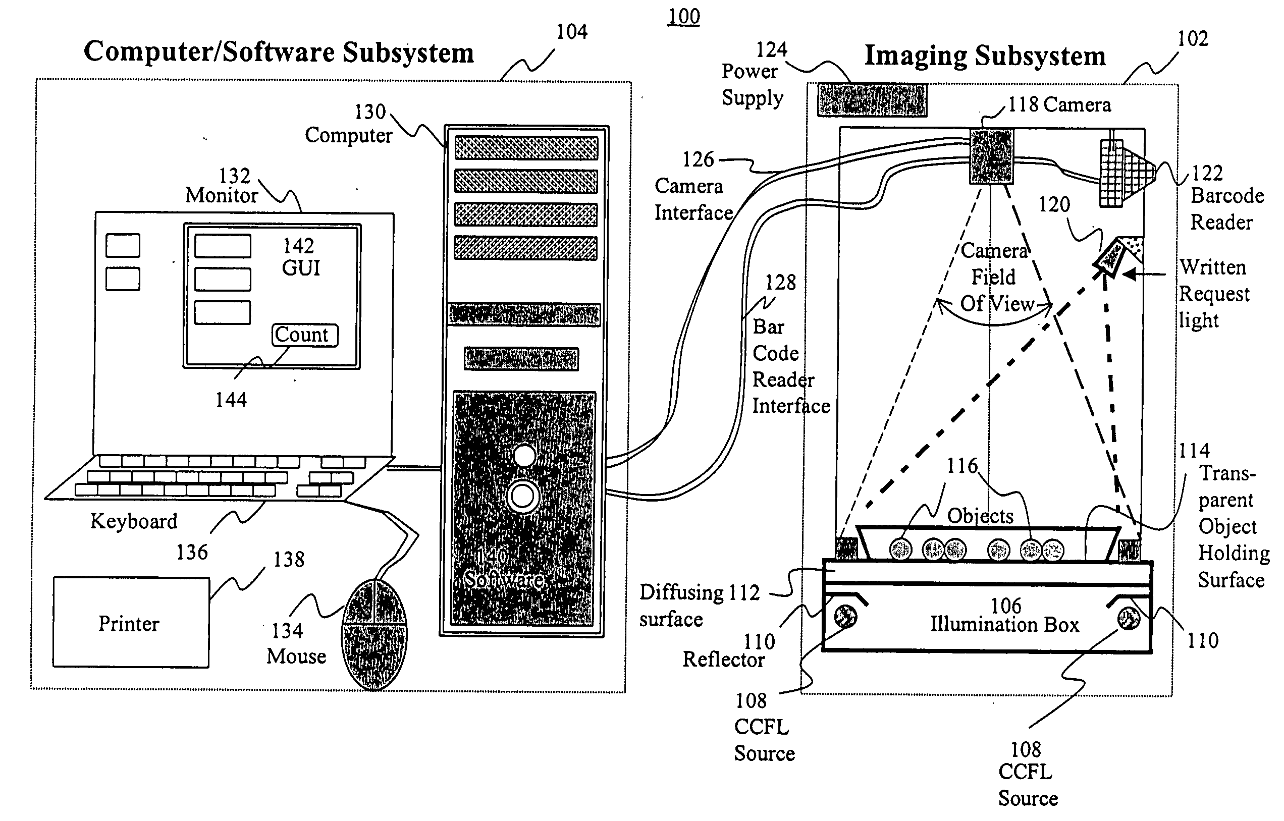
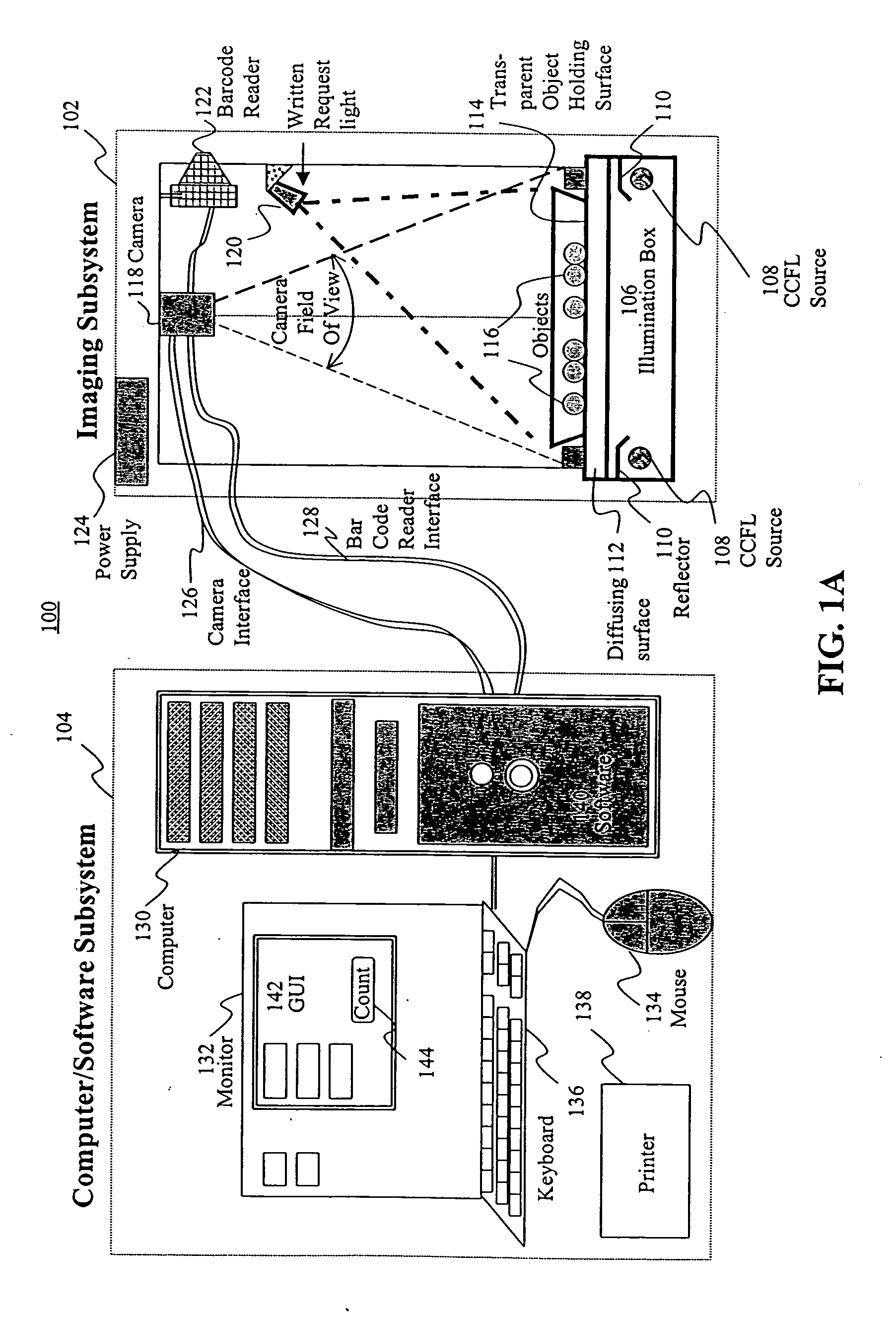
[0036] In the present invention, object holding surface 114 is a multiplicity of trays carried by a conveyor (not shown) or a rotary mechanism (not shown) and passing over diffusing surface 112 in a stop-and-go motion. The conveyor or rotary mechanism advances the trays and stops when each tray reaches an appropriate imaging position (i.e., in the field of view of the digital imaging unit), thereby allowing imaging subsystem 102 to be used in a production environment to count the objects in each tray. In these stop-and-go conveyor or rotary configurations, electromagnetic radiation sources 108 provide continuous exposure to be detected by, for example, a CCD-based digital camera.

third embodiment

[0037] In a third embodiment, also suitable for a production environment, a conveyor or rotary mechanism continuously moves trays holding objects 116, and digital imaging unit 118 is a CCD-based digital camera. This embodiment requires a short duration flash exposure of the radiation provided by sources 108. This flash exposure mode allows a sharp digital image to be captured by CCD-based digital camera 118, with almost no fuzzy edges developing at the edges of the objects normal to the direction of the continuous motion of the conveyor / rotary mechanism. The shorter the duration of the flash, the less visible this fuzzy edge effect will be.

[0038] In a fourth embodiment of this invention, which is again suitable for a production environment, trays holding objects 116 move continuously in uniform motion by a conveyor or rotary mechanism, and digital imaging unit 118 includes a linear lens array (e.g., Selfoc lens array), aligned with a linear photodiode array. In the fourth embodiment...


PUM


Abstract

A system for automatic counting of non-overlapping objects irrespective of shape, size, and color is provided by imaging and computer subsystems. Objects to be counted are placed on a transparent surface disposed on a diffusing surface uniformly irradiated by electromagnetic radiation sources. Low intensity object shadows and high intensity object background regions are digitally imaged. The digital image is converted by a computing unit to a binary image and subjected to the Distance Transform to determine a count of the objects. Object identification verification is provided by comparing identification information obtained from a bar code associated with a supply container of the objects and identification information obtained from a digitally imaged written request.

Description

Technical Field [0001] This invention relates in general to automatically counting and verifying objects, and in particular, to automatically counting non-overlapping objects and verifying the identification of the counted objects by employing a digital imaging unit connected to a computing unit. BACKGROUND OF THE INVENTION [0002] Many applications, including the handling of pharmaceutical pills and capsules, include a counting of objects. Assessments of object counting techniques focus on various aspects, including accuracy, speed, cost, and reliability. Object counting methods can be placed into three broad categories: (1) manual methods; (2) semi-automated methods; and (3) automated methods. [0003] The manual methods include, for example, taking a quantity of the desired objects from a bulk supply container, placing them onto a surface, and separating the desired number of objects using a combination of human manual skills and human perception. This counting process can include c...

Claims


Application Information

Patent Timeline
Patent Type & Authority Applications(United States)
IPC IPC(8): G06K9/00G06V10/141
CPCG06K9/2027G06K9/3241G06M11/00G06M1/101G06K2017/0051G06V10/141G06V10/255G06V20/66
Inventor ATEYA, ANTOUN
Owner ATEYA ANTOUN
Why Eureka
Try Eureka