Apparatus, method and program performing image collation with similarity score as well as machine readable recording medium recording the program

an image collation and similarity score technology, applied in the field of apparatus, method and program performing image collation with similarity score and machine readable recording medium recording the program, can solve the problems of inability to ensure, foregoing image collating apparatus, and determination of match/mismatch between, so as to suppress the disadvantageous determination error, suppress the increase in storage capacity, and achieve the effect of fast collation

Inactive Publication Date: 2006-03-02
SHARP KK
View PDF3 Cites 17 Cited by
  • Summary
  • Abstract
  • Description
  • Claims
  • Application Information

AI Technical Summary

Benefits of technology

[0032] According to the invention, since the partial area overlapping with the partial areas set in the first image and neighboring to each other is set as the partial area including the boundary between the foregoing neighboring partial areas, it is possible to set the partial area of a size required for ensuring a collation accuracy, and to set the partial areas of the number required for ensuring the collation accuracy. Further, the partial area set in the overlapping fashion is the partial area including the boundary between the neighboring partial areas, and the determination of match/mismatch is performed on the images including the image data of this partial area. Therefore, the continuity of the image at the boundary between the partial areas neighboring to each other can be reflected in the determination of match/mismatch between the images so that it is possible to suppress a disadvantageous determination error which may be caused by the fact that the continuity at t

Problems solved by technology

Accordingly, when the image obtained by a sensor has an excessively small size, it is impossible to ensure a sufficient number of partial areas if the apparatus is configured to prevent mutual overlapping of the partial areas, as is done in the foregoing image collating apparatus, while satisfying the foregoing conditions of the size of the

Method used


Image

  • Apparatus, method and program performing image collation with similarity score as well as machine readable recording medium recording the program
  • Apparatus, method and program performing image collation with similarity score as well as machine readable recording medium recording the program
  • Apparatus, method and program performing image collation with similarity score as well as machine readable recording medium recording the program

Examples


first embodiment

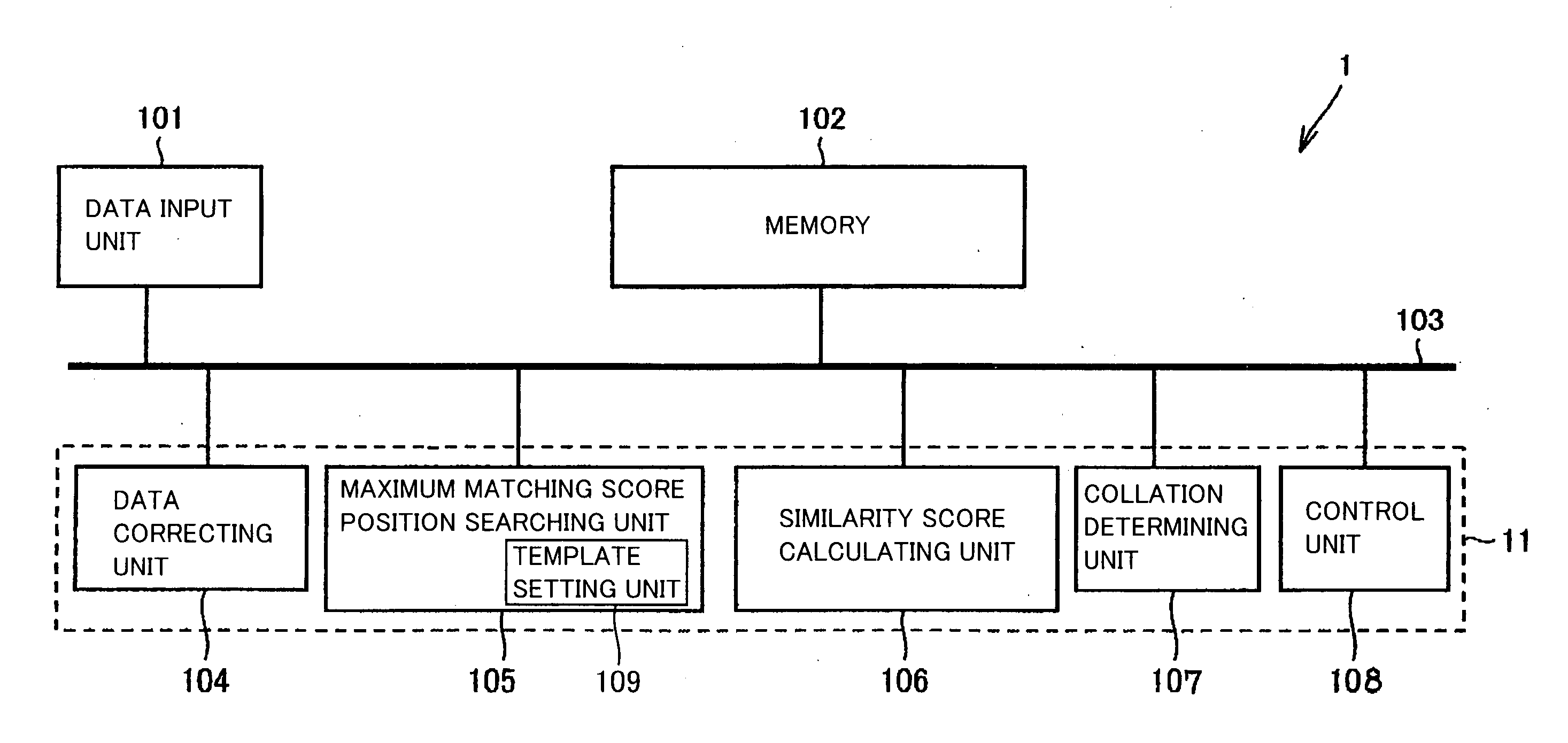
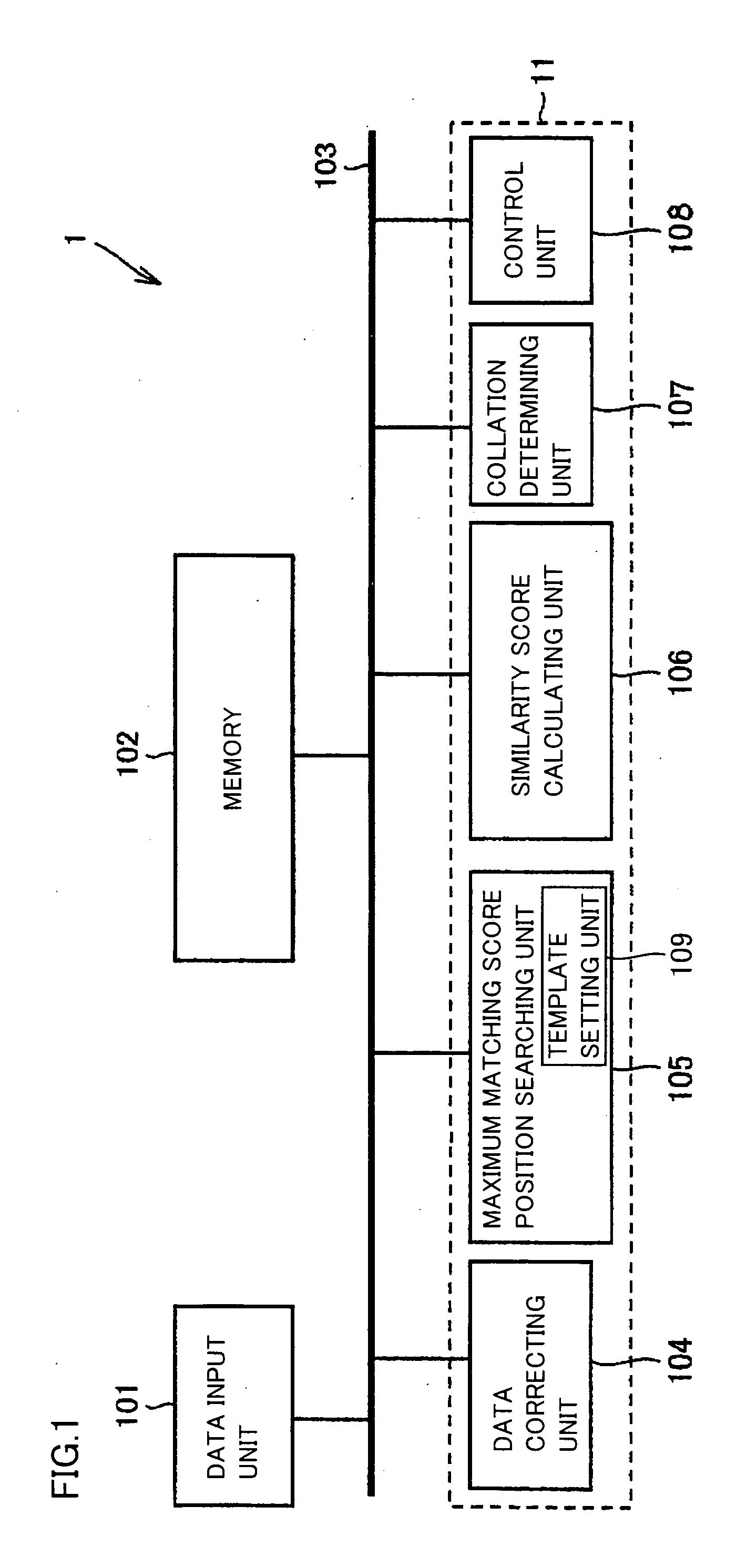
[0059]FIG. 1 illustrates a block structure of an image collating apparatus 1 according to a first embodiment.

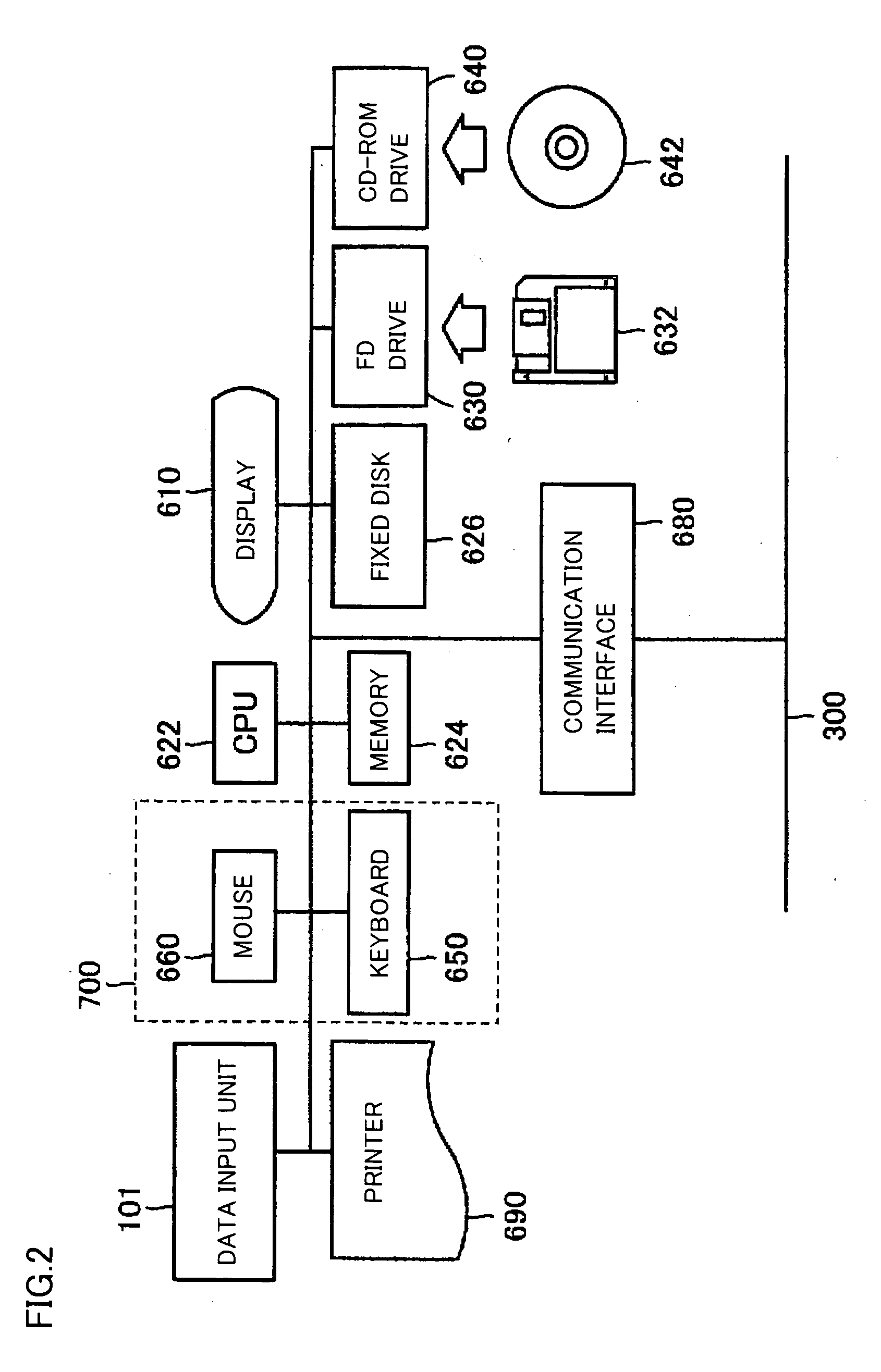
[0060]FIG. 2 illustrates a computer equipped with the image collating apparatus according to each embodiment. FIG. 2 shows a configuration of a computer in which the image collating apparatus in accordance with various embodiments is mounted. Referring to FIG. 2, the computer includes an image input unit 101, a display 610 such as a CRT (Cathode Ray Tube) or a liquid crystal display, a CPU (Central Processing Unit) 622 for central management and control of the computer itself, a memory 624 including an ROM (Read Only Memory) or an RAM (Random Access Memory), a fixed disk 626, an FD drive 630 on which an FD (flexible disk) 632 is detachably mounted and which accesses to FD 632 mounted thereon, a CD-ROM drive 640 on which a CD-ROM (Compact Disc Read Only Memory) 642 is detachably mounted and which accesses to the mounted CD-ROM 642, a communication interface 680 for connecting...

second embodiment

[0093] In the first embodiment already described, after the partial areas neighboring to each other are set in the image, the boundary-including partial area is set in the overlapping manner on the above partial area, and the setting of the partial area ends when the area allowing the setting of the boundary-including partial area is no longer left. In contrast to this control, a second embodiment performs the control such that setting of the partial areas ends when the partial areas equal in number to a predetermined value of variable “n” are set. This second embodiment will now be described with reference to FIGS. 8-12. FIG. 8 illustrates a structure of an image collating apparatus 2 according to the second embodiment. Image collating apparatus 2 has the same structure as image collating apparatus 1 except for that similarity score calculating unit 106 of image collating apparatus 1 is replaced with a similarity score collating unit 113, and template setting unit 109 is replaced w...

third embodiment

[0107] In the first and second embodiments, images “A” and “B” to be collated are provided from image input unit 101. In a third embodiment, however, one of two images to be collated is registered in advance, and only the other image is provided.

[0108]FIG. 13 is a block diagram of an image collating apparatus according to the third embodiment. Image collating apparatus 3 in FIG. 13 differs from image collating apparatus 1 in FIG. 1 in that image collating apparatus 3 includes a registered data storing unit 202 in addition to the structures of image collating apparatus 1, and further includes a collation processing unit 12 in place of collation processing unit 11. In addition to the structure of collation processing unit 11, collation processing unit 12 has a fingerprint registering unit 206 and a registered data reading unit 207. Further, maximum matching score position searching unit 105 has a template setting unit 111 instead of template setting unit 109.

[0109] Registered data s...


PUM


Abstract

Rectangular partial areas “Ri” for use in template matching in a process of determining match/mismatch between fingerprint images are spread adjacently to each other in one of the images. A boundary-including partial area is set in a portion including a crossing point of cross-shaped boundaries defined by the four neighboring partial areas. The plurality of partial areas formed of the neighboring partial areas and the boundary-including partial area are used as a template so that the number of the partial areas can be increased while ensuring a certain size of the partial area. Further, the boundary-including partial area covers the boundary between the neighboring partial areas so that continuity of image data at the boundary between the neighboring partial areas can be reflected in the determination of the match/mismatch between the images.

Description

[0001] This nonprovisional application is based on Japanese Patent Application No. 2004-250345 filed with the Japan Patent Office on Aug. 30, 2004, the entire contents of which are hereby incorporated by reference. BACKGROUND OF THE INVENTION [0002] 1. Field of the Invention [0003] The present invention relates to an apparatus, method and program for collating images of fingerprints or the like with each other and thereby determining whether the fingerprints or the like match with each other or not, and also relates a machine readable recording medium storing the program. In particular, the invention relates to an apparatus, method and program collating one item of input data with a plurality of items of reference data, and also relates to a machine readable recording medium storing the program. [0004] 2. Description of the Background Art [0005] Japanese Patent Laying-Open No. 2003-323618 has disclosed an image collating apparatus which performs collation of a plurality of items of ...

Claims


Application Information

Patent Timeline
IPC IPC(8): G06K9/62
CPCG06K9/00087G06V40/1365
Inventor ITOH, YASUFUMIYUMOTO, MANABUONOZAKI, MANABU
Owner SHARP KK
Why Eureka
Try Eureka