Fiber optic receptacle and plug assemblies with alignment and keying features

Active Publication Date: 2006-03-02
CORNING OPTICAL COMM LLC
View PDF26 Cites 56 Cited by
  • Summary
  • Abstract
  • Description
  • Claims
  • Application Information

AI Technical Summary

Benefits of technology

[0010] To achieve the foregoing and other objects, and in accordance with the purposes of the invention as embodied and broadly described herein, the present invention provides various embodiments of fiber optic receptacle and plug assemblies adapted to receive like optical connector configurations. Thus, the present invention provides fiber optic receptacle and plug assembli

Problems solved by technology

In addition to requiring the use of different fiber optic receptacles and plugs based upon the specific type of optical connector, conventional receptacle and plug assemblies are relatively large in size.
Current smaller assemblies, however, are not able to satisfy the high tensile loads required for FTTx installations, including the 600 lbs. drop cable pull test requirement.
Exposure to adve

Method used


Image

  • Fiber optic receptacle and plug assemblies with alignment and keying features
  • Fiber optic receptacle and plug assemblies with alignment and keying features
  • Fiber optic receptacle and plug assemblies with alignment and keying features

Examples


Example

[0028] The present invention will now be described more fully hereinafter with reference to the accompanying drawings in which exemplary embodiments of the invention are shown. However, this invention may be embodied in many different forms and should not be construed as limited to the embodiments set forth herein. These exemplary embodiments are provided so that this disclosure will be both thorough and complete, and will fully convey the scope of the invention to those skilled in the art. Like reference numbers refer to like elements throughout the various drawings.

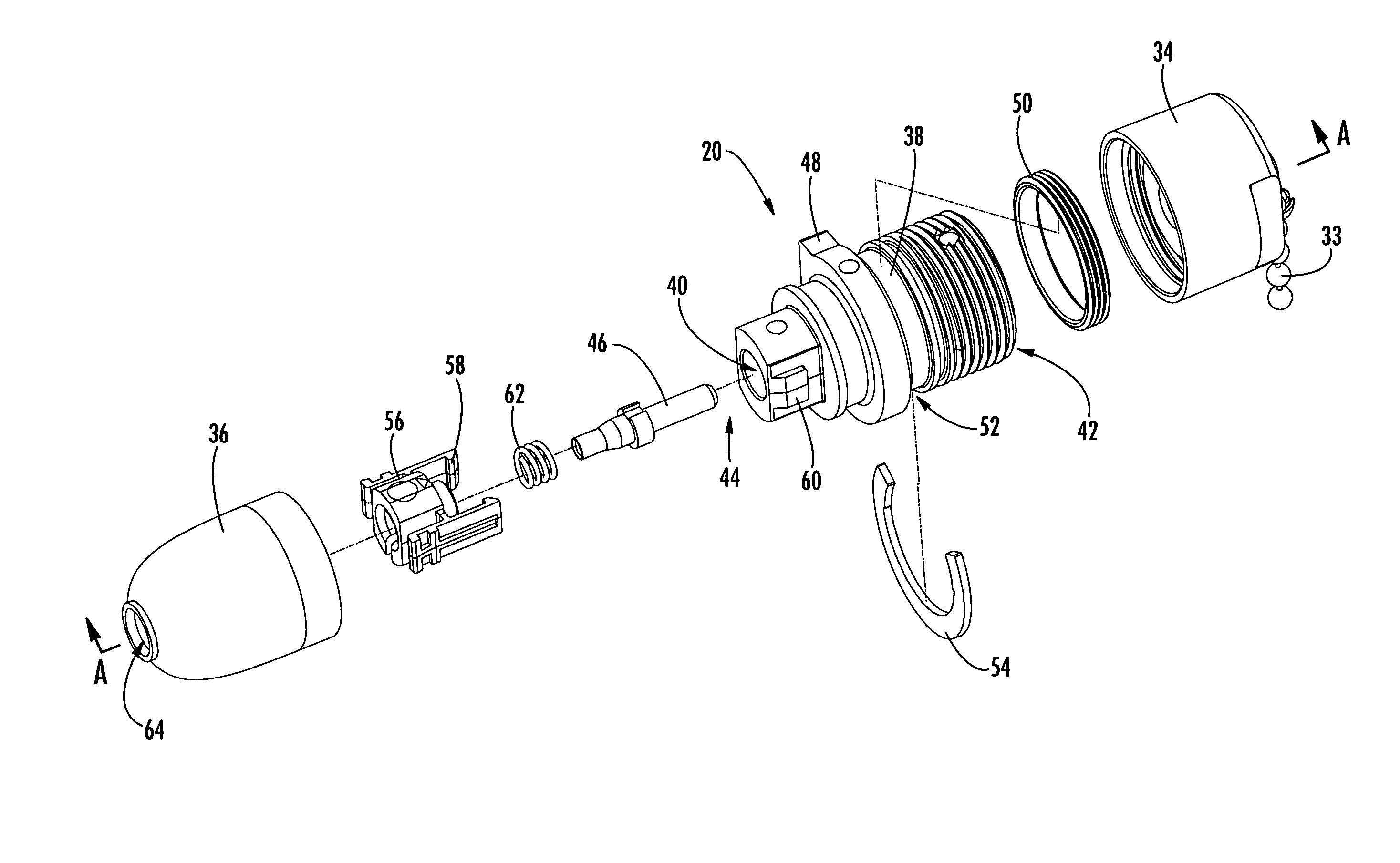
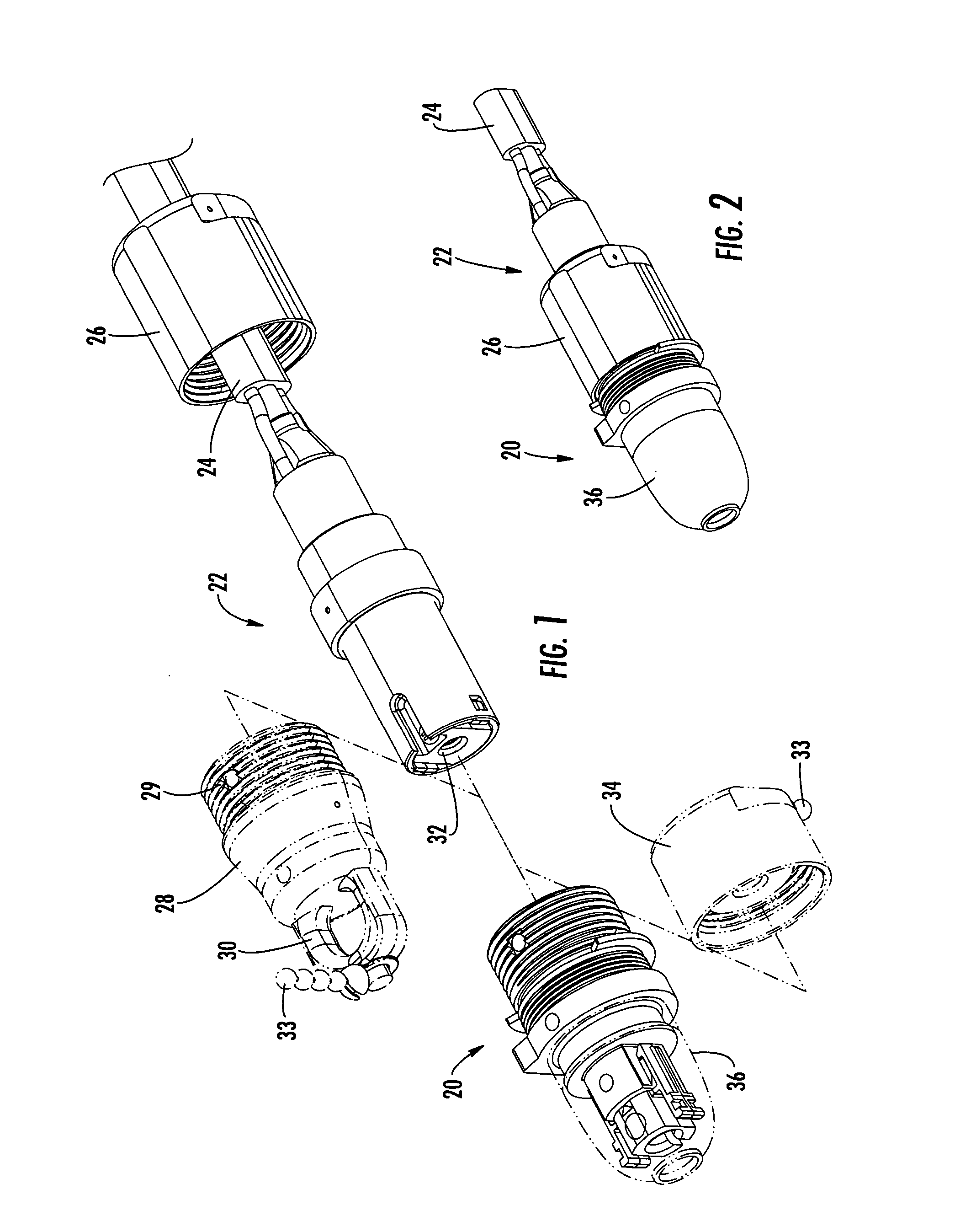
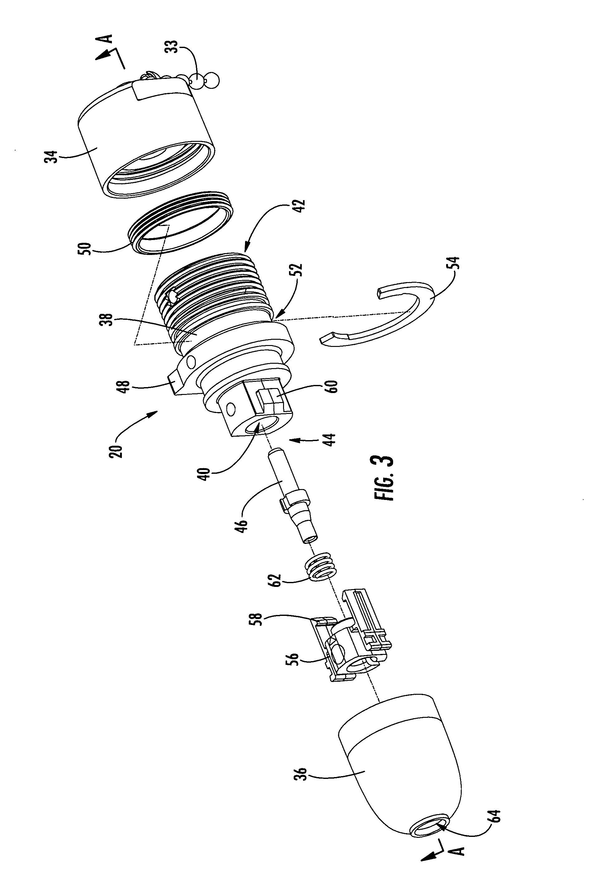
[0029] In the various embodiments described below, the present invention comprises fiber optic receptacle and plug assemblies including one or more optical connectors for interconnecting optical fibers within a communications network. The receptacle portion of each assembly is designed such that it may be mounted in a wall of an enclosure or similar structure defining an external wall through which one or more optical ...


PUM


Abstract

A fiber optic receptacle and plug assembly comprising a fiber optic receptacle adapted to be mounted within a connector port of a network connection terminal and a fiber optic plug mounted upon an end of a fiber optic cable, wherein the fiber optic receptacle and the fiber optic plug comprise complimentary alignment and keying features that allow the fiber optic receptacle to receive only a fiber optic plug of like ferrule configuration. The fiber optic plug comprises an alignment sleeve operable for receiving and optically connecting at least one plug ferrule and at least one receptacle ferrule. The receptacle is suitable for use in enclosures requiring a minimal receptacle penetration depth, wherein the fiber optic receptacle comprises a shoulder that is secured against an inner wall of the enclosure to provide strain relief against cable pulling forces of up to about 600 lbs.

Description

CROSS-REFERENCE TO RELATED APPLICATIONS [0001] This application is a continuation-in-part of U.S. application Ser. No. 10 / 924,525 filed Aug. 24, 2004, entitled “FIBER OPTIC RECEPTACLE AND PLUG ASSEMBLIES.”BACKGROUND OF THE INVENTION [0002] 1. Field of the Invention [0003] The present invention relates generally to assemblies for interconnecting optical fibers, and more specifically, to fiber optic receptacle and plug assemblies with alignment and keying features for interconnecting optical fibers within a fiber optic communications network. [0004] 2. Description of the Related Art [0005] Optical fiber is increasingly being used for a variety of broadband applications including voice, video and data transmissions. As a result, fiber optic communications networks include a number of interconnection points at which optical fibers are interconnected with other optical fibers. Fiber optic networks also include a number of connection terminals, examples of which include, but are not limit...

Claims


Application Information

Patent Timeline
IPC IPC(8): G02B6/36
CPCG02B6/3831G02B6/3847G02B6/4465G02B6/389G02B6/3879G02B6/3888G02B6/545
Inventor THEUERKORN, THOMASNORRIS, MARTIN E.
Owner CORNING OPTICAL COMM LLC
Why Eureka
Try Eureka