
Fuel cell apparatus improvements

a fuel cell and apparatus technology, applied in the field of electrochemical cells, can solve the problems of complex sealing arrangement, design can be quite complex, and the seals have to be of a relatively complex configuration, so as to improve the operating efficiency of the fuel cell, prevent electrical shorting, and increase the surface area

Inactive Publication Date: 2006-03-02
HYDROGENICS CORP
View PDF2 Cites 16 Cited by
  • Summary
  • Abstract
  • Description
  • Claims
  • Application Information

AI Technical Summary

Benefits of technology

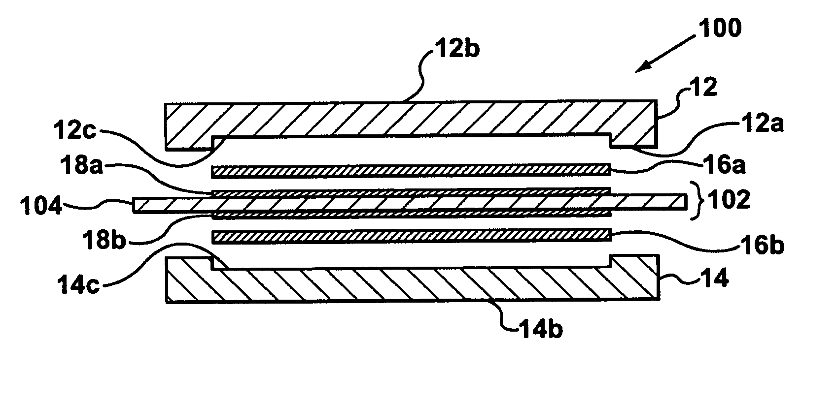
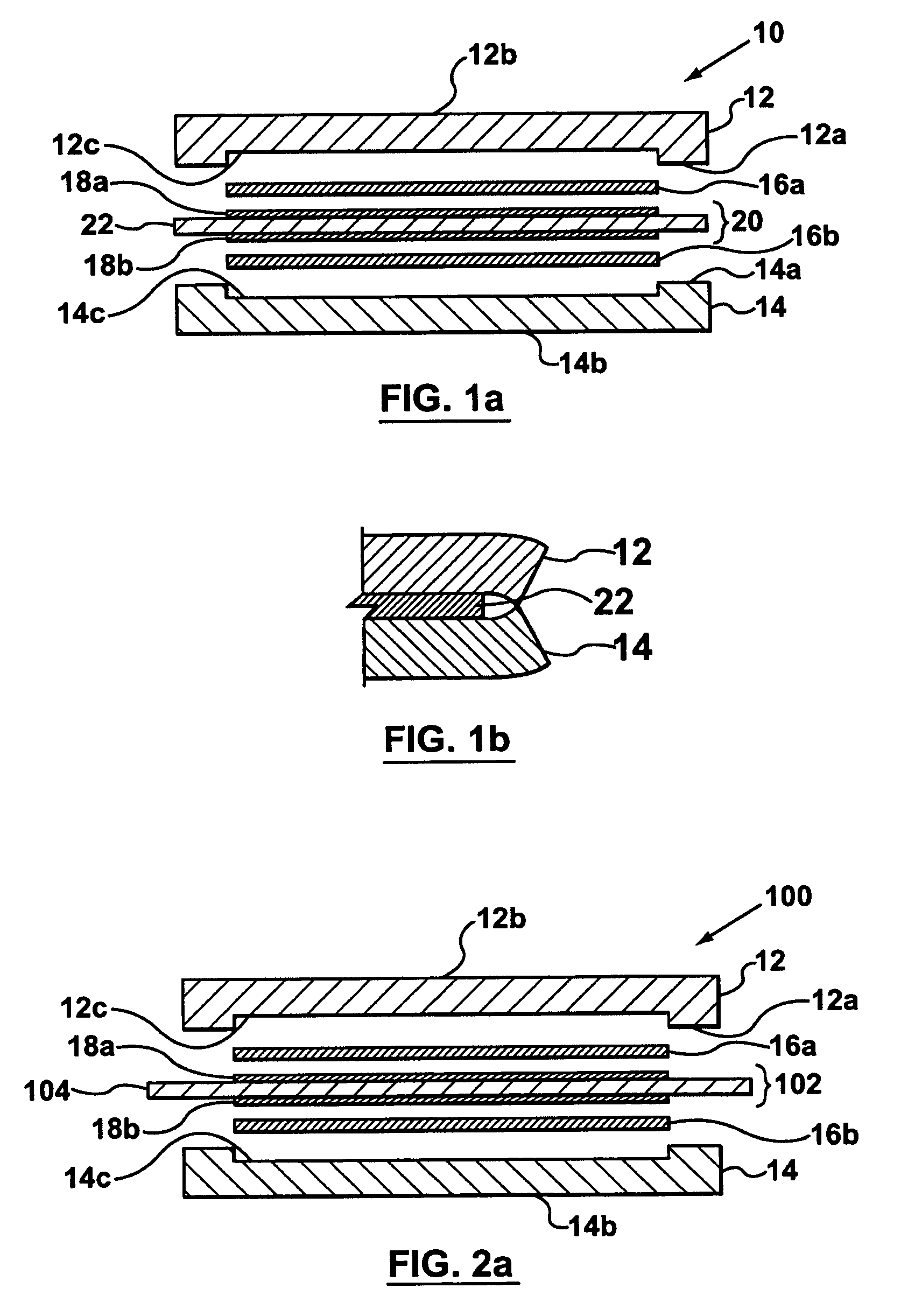
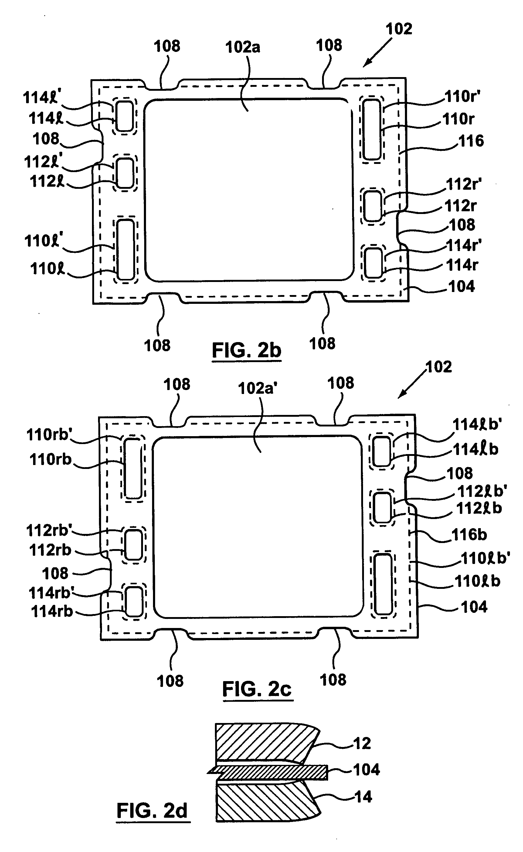
[0012] The inventors have made several structural improvements to the components of a fuel cell that can be used in isolation or in combination, to address one or more of the above-noted shortcomings and to improve the operating efficiency of a fuel cell. In one instance, the inventors have found that it is advantageous to increase the surface area of the MEA relative to the surface area of the flow field plates. In this case, during fuel cell assembly or maintenance, if the flow field plates of a given fuel cell bend, due to stress, the flow field plates will advantageously touch the MEA rather than touch each other which will prevent electrical shorting. The extended MEA may include alignment notches in certain locations if alignment rods are used during fuel cell stack assembly.
[0013] In an alternative, that can be practiced in combination or instead of the extension of the MEA surface area, the inventors have found that it is advantageous to chamfer the edges of the flow field plates. The inventors have found that using chamfered edges reduces the chance that the flow field plates of a given fuel cell will short if one or more of the flow field plates bend. The edges of the flow field plate may be chamfered by making a straight cut at a desired angle (this is referred to as a straight chamfer). Alternatively, the edges of the flow field plate may be chamfered by making a round cut using a desired radius of curvature (this is referred to as a round chamfer).

Problems solved by technology

While this does provide a single unit capable of generating useful amounts of power at usable voltages, the design can be quite complex and can include numerous elements, all of which must be carefully assembled.
Moreover, these seals have to be of a relatively complex configuration.
In particular, as detailed below, the flow field plates, for use in the fuel cell stack, have to provide a number of functions and a complex sealing arrangement is required.
It will thus be appreciated that the sealing requirements are complex and difficult to meet.
This allows for a more compact stack (thinner plates) but may provide less than satisfactory cooling.
A problem in many electrochemical cell designs is that each individual flow field plate is relatively fragile, since it is necessarily made from an electrical conductive material such as graphite.
The flow field plate is thus prone to bending during the assembly process.
Accordingly, when either of the flow field plates, for a particular fuel cell, gets slightly bent in the assembly process or during regular use, the probability that the edges of the flow field plates will touch each other resulting in a short increases.
Shorting may also arise when gaskets are used, since the gasket may shift position during assembly or use or the gasket may become over-compressed.
Shorting is not desirable, since a short will reduce the electrical energy generation of the fuel cell stack as well as possibly damage one or more of the components of the fuel cell stack.
Needless to say, such an event also increases the amount of maintenance that must be performed on the fuel cell stack.

Method used


Image

  • Fuel cell apparatus improvements
  • Fuel cell apparatus improvements
  • Fuel cell apparatus improvements

Examples


Embodiment Construction

[0032] In the following detailed description, numerous specific details are set forth in order to provide a thorough understanding of the invention. However, it will be understood by those of ordinary skill in the art that the invention may be practiced without these specific details. In other instances, well-known methods, procedures and components have not been described in detail so as not to obscure the invention. Further, it will be appreciated that for simplicity and clarity of illustration, elements shown in the figures have not necessarily been drawn to scale. For example, the dimensions of some of the elements may be exaggerated relative to other elements for clarity. Further, where considered appropriate, reference numerals may be repeated among the figures to indicate corresponding or analogous elements.

[0033] There are various known types of electrochemical cells. Examples of such cells currently receiving great interest in the industry are fuel cells and electrolyzer c...


PUM


Abstract

An electrochemical cell assembly with structural improvements for improving cell operation. The electrochemical cell assembly may include at least one of an extended MEA and chamfered edges on the flow field plates for preventing the shorting of the anode and cathode flow field plates. Further, the flow field plates may include a pocket for providing an appropriate space to accommodate a gas diffusion media and applying an appropriate amount of compression to the gas diffusion media.

Description

FIELD OF THE INVENTION [0001] This invention relates to electrochemical cells such as fuel cells and electrolyzer cells. In particular, this invention relates to improvements in the structure of fuel cell components. BACKGROUND OF THE INVENTION [0002] Fuel cells are used to generate electrical energy using various fuels, whilst electrolyzer cells are used to generate hydrogen gas from hydrogen containing fuels. One form of fuel cell that is currently believed to be practical for usage in many applications is a fuel cell employing a proton exchange membrane (PEM). A PEM fuel cell enables a simple, compact fuel cell to be designed, which is robust, which can be operated at temperatures not too different from ambient temperatures and which does not have complex requirements with respect to fuel, oxidant and coolant supplies. [0003] Conventional fuel cells generate relatively low voltages. In order to provide a useable amount of power, fuel cells are commonly configured into fuel cell s...

Claims


Application Information

Patent Timeline
IPC IPC(8): H01M8/02H01M8/10H01M4/94
CPCH01M8/0247H01M8/0273Y02E60/521H01M8/242H01M8/1004Y02E60/50H01M8/2432
Inventor FRANK, DAVIDJOOS, NATHANIEL IANDZAMARIJA, MARIOCANDIDO, RAYMONDMAZZA, ANTONIO GENNARO
Owner HYDROGENICS CORP
Learn More