Balanced transmission cable connector
a technology of transmission cable and connector, which is applied in the direction of electrically conductive connections, printed circuit aspects, coupling device connections, etc., can solve problems such as the inability to adjust the transmission method, and achieve the effect of minimizing the crosstalk between the output signal and the input signal
- Summary
- Abstract
- Description
- Claims
- Application Information
AI Technical Summary
Benefits of technology
Problems solved by technology
Method used
Image
Examples
embodiment 1
[0040]FIGS. 8 through 10 show a part of a balanced transmission cable connector 30A according to an embodiment 1 of the present invention. Lines X1-X2, Y1-Y2 and Z1-Z2 respectively indicate the width direction of the cable connector 30A, the longitudinal direction thereof and the height direction thereof. Y1 and Y2 respectively indicate the rear side and the front side. When referring to arrangement of contacts, the lines Z1-Z2 and X1-X2 respectively indicate the column direction and the row direction. FIG. 8 is a top perspective view of the cable connector 30A, and FIG. 9 is a bottom perspective view of the cable connector 30A. FIG. 10 is a side elevational view showing the cable connector 30A. FIG. 11 is an illustration showing a cable connected to an end of a relay board 200.
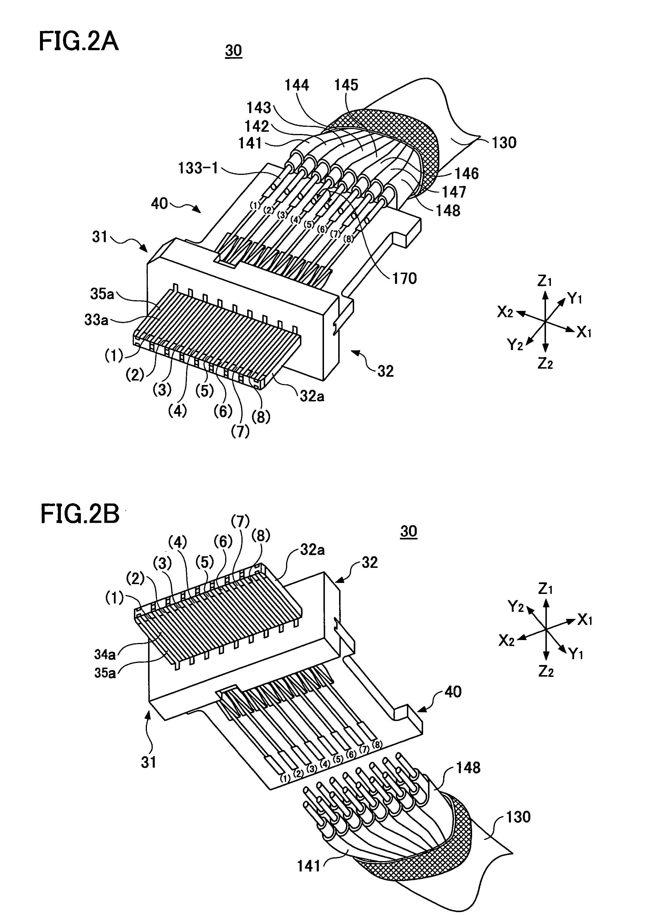
[0041] In FIGS. 8 through 11, the components corresponding to those in FIGS. 2A through 4 are denoted by the same reference numerals.
[0042] The cable connector 30A is substantially the same as the cable con...
embodiment 2
[0083]FIGS. 15 and 16 are illustrations each showing a part of a balanced transmission cable connector 30B according to an embodiment 2 of the present invention.
[0084] The cable connector 30B is substantially the same as the cable connector 30 shown in FIGS. 2A and 2B except having a shield member 400.
[0085] The shield member 400, as shown in FIG. 18 in detail, has a clamp section 401 for clamping a relay board 40. The length L1 of the shield member 400 is longer than the length L2 of the part of first and second shielded signal wires 132-1 and 132-2 extending out of an end of a metal tape 135.
[0086] The shield member 400 is mounted between a signal output pair wire 144 and a signal input pair wire 145 adjacent thereto. The clamp section 401 is arranged to fit and clamp the Y1 side end of the relay board 40 so that the shield member 400 is electrically connected to ground patterns 80 and 120.
[0087] The shield member 400 shields between the shielded first and second signal wires ...
PUM
 Abstract
Description
Claims
Application Information
 - R&D
- Intellectual Property
- Life Sciences
- Materials
- Tech Scout
- Unparalleled Data Quality
- Higher Quality Content
- 60% Fewer Hallucinations
Browse by: Latest US Patents, China's latest patents, Technical Efficacy Thesaurus, Application Domain, Technology Topic, Popular Technical Reports.
© 2025 PatSnap. All rights reserved.Legal|Privacy policy|Modern Slavery Act Transparency Statement|Sitemap|About US| Contact US: help@patsnap.com


