Method and device for controlling gear shift of mechanical transmission

a transmission control and gear shift technology, applied in the direction of electric control, machines/engines, instruments, etc., can solve the problems of difficult to satisfactorily transfer the driving torque of a torque converter, the delicate control of a half-clutch state, and the large amount of transmission driving torque, etc., to achieve the effect of shortening the gear shift tim

Inactive Publication Date: 2006-03-02
MITSUBISHI FUSO TRUCK AND BUS CORPORATION
View PDF10 Cites 24 Cited by
  • Summary
  • Abstract
  • Description
  • Claims
  • Application Information

AI Technical Summary

Benefits of technology

[0009] The present invention has been made in order to solve these problems, and its object is to provide a transmission control method for a mechanical transmission, capable of shortening a gear shift time without undergoing a shock attributed to gear disengagement, and an apparatus therefor.

Problems solved by technology

In large vehicles, such as buses, trucks, etc., the transfer amount of driving torque is so large that it is hard for a torque converter to transfer the driving torque satisfactorily.
In automatically controlling the friction clutch in accordance with the gear shift in the mechanical transmission, however, delicate control in a half-clutched state is difficult.
Therefore, it can be supposed that, depending on the engine torque of the internal combustion engine varying with the increase or decrease of the fuel supply, the gear disengagement is performed inevitably even if the transfer torque is not fully cut off, in many cases.
If the gear disengagement is performed in this manner without fully cutting off the transfer torque, and if the transfer torque is relatively high, a shock is generated by the gear disengagement, unfavorably giving a feeling of wrongness to occupants of the vehicle.

Method used


Image

  • Method and device for controlling gear shift of mechanical transmission
  • Method and device for controlling gear shift of mechanical transmission
  • Method and device for controlling gear shift of mechanical transmission

Examples


first embodiment

[0055] A first embodiment will be described first.

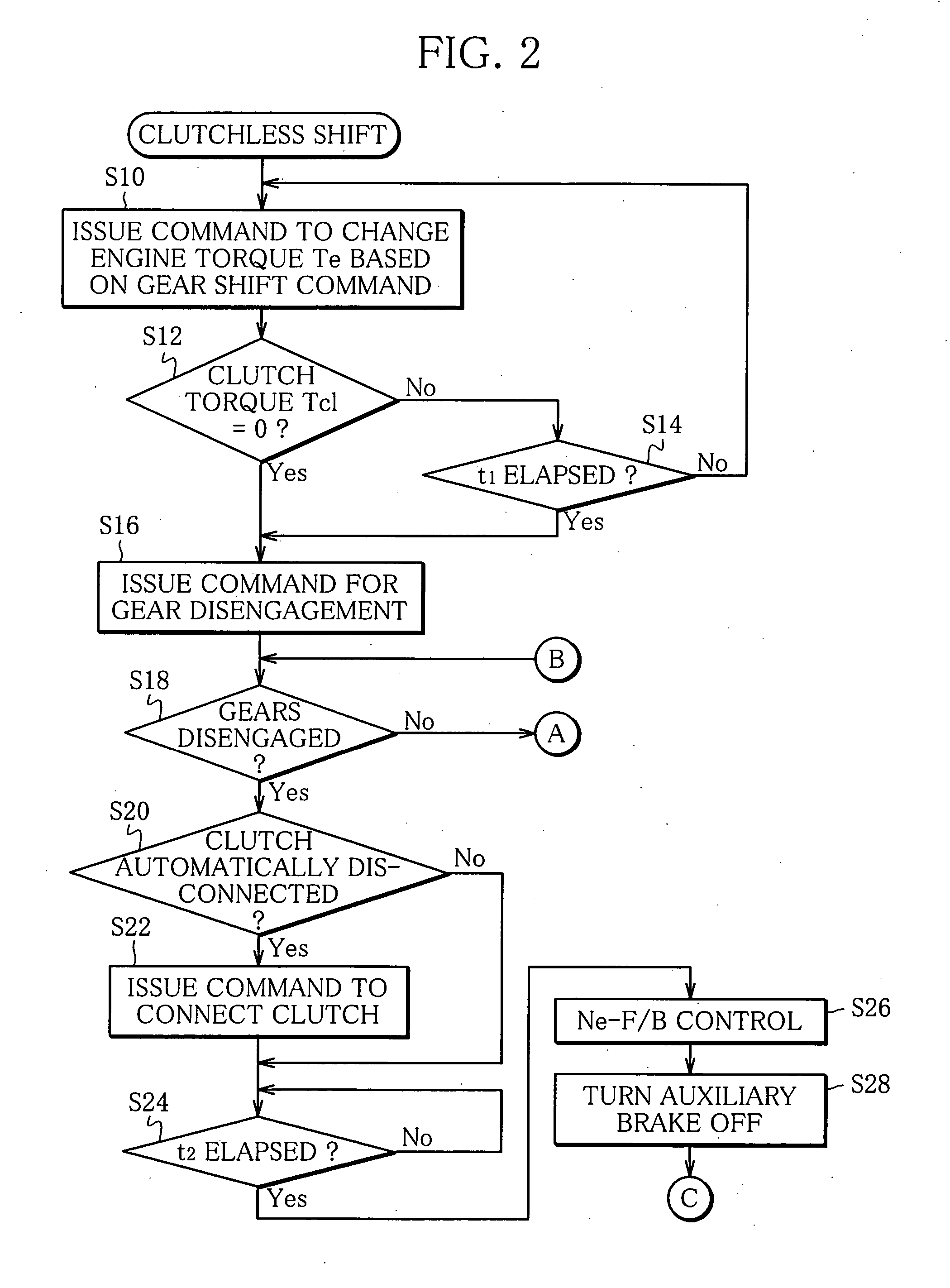
[0056] Referring now to FIGS. 2 to 5, there is shown a flow chart for control routines of clutchless shift control according to the present invention, and the following description is based on this flowchart.

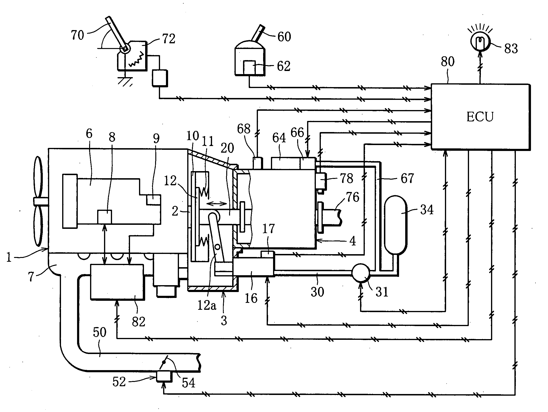
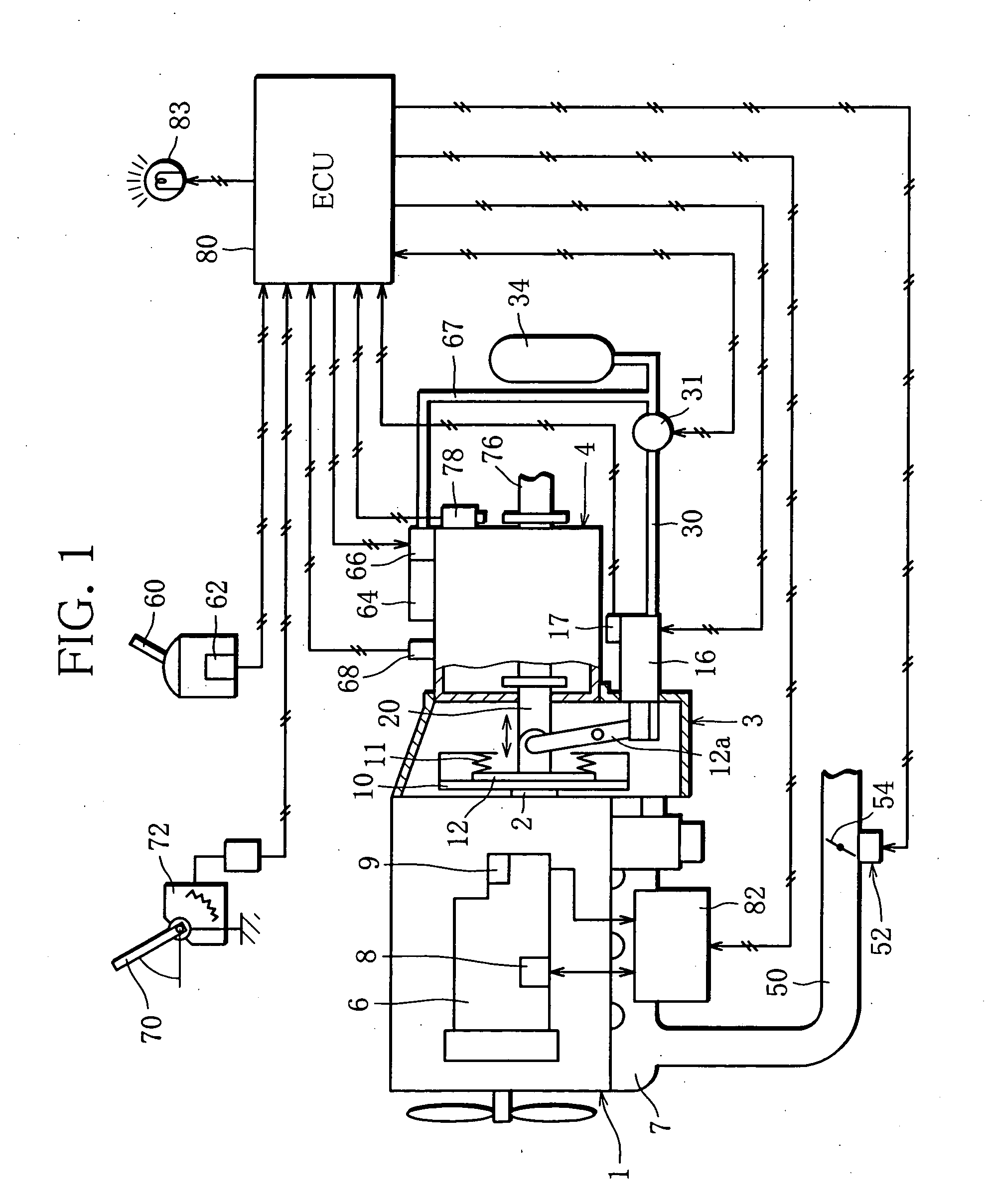
[0057] In Step S10 of FIG. 2, a command is issued to change the engine torque Te (engine torque control means) in response to a gear shift command from the ECU 80. More specifically, in doing this, the engine 1 is controlled to change the engine torque Te so that the value of a transfer torque of the clutch unit 3, i.e. a clutch torque Tcl between the flywheel 10 and the clutch plate 12, is 0 or near 0.

[0058] More specifically, the engine torque Te to be changed is obtained as follows so that the value of the clutch torque Tcl is, for example, 0, according to a motion equation (equation (1)) for a range from the engine 1 to the flywheel 10 and a motion equation (equation (2)) for a range from the clutch plate 12 to each wheel a...

second embodiment

[0111] The following is a description of a

[0112] Referring to FIG. 6, there is shown a flowchart illustrating a control routine of clutchless shift control according to the second embodiment of the present invention. The second embodiment will now be described with reference to this flowchart. Same step numbers are used to designate the same portions as those of the first embodiment, and a description of those portions will be omitted. Only those portions which are different from the counterparts of the first embodiment will be described in the following.

[0113] In Step S12′ following Step S10, it is determined whether or not a predetermined period t0 has elapsed since the change of the engine torque Te based on a gear shift command. More specifically, the engine torque Te is obtained, and the fuel injection quantity is changed by controlling the control rack so that the engine torque Te can be obtained. If the predetermined period to elapses thereafter, the value of the clutch torq...


PUM


Abstract

Provided are a transmission control method for a mechanical transmission, capable of shortening a gear shift time without undergoing a shock attributed to gear disengagement, and an apparatus therefor. The transmission control apparatus comprises engine torque control means (S10) for controlling an engine torque generated by an internal combustion engine so that the value of a transfer torque of a friction clutch is 0 or near 0 when a gear shift of the mechanical transmission is required, gear shift allowing means (S12) for aloowing the gear shift of the mechanical transmission when the engine torque is controlled by the engine torque control means so that the value of the transfer torque is 0 or near 0, and gear shift executing means (S16) for disengaging and engaging gears with the clutch kept connected when the gear shift is allowed by the gear shift allowing means.

Description

TECHNICAL FIELD [0001] The present invention relates to a method and an apparatus for transmission control for a mechanical transmission, and more specifically, to a technique for performing a gear shift without connecting or disconnecting a friction clutch. BACKGROUND ART [0002] Transmissions of which gear shift operation is automated are frequently used as vehicular transmissions. In large vehicles, such as buses, trucks, etc., the transfer amount of driving torque is so large that it is hard for a torque converter to transfer the driving torque satisfactorily. For example, a mechanical transmission, which is designed so that gear shift operation for a manual mechanical transmission is automated, is employed. [0003] This mechanical transmission is configured to achieve a gear shift by automatically carrying out gear engagement and gear disengagement. As for a friction clutch, it is configured to be automatically connected and disconnected in accordance with the gear shift or a sto...

Claims


Application Information

Patent Timeline
Patent Type & Authority Applications(United States)
IPC IPC(8): G06F17/00B60W10/02B60W10/04B60W10/06B60W10/10B60W10/11F02D29/00F02D41/02F02D41/04F16H59/14F16H59/40F16H59/42F16H61/02F16H61/04F16H63/50
CPCB60K2741/085B60W10/06B60W10/11B60W30/19F02D41/023F16H2306/50F02D2250/21F16H61/0206F16H63/502F16H2306/42F16H2306/46F02D2250/18F02D45/00
Inventor IKEYA, KOUICHIERITATE, KAZUNOBUSHIRASAWA, TOSHIKUNI
Owner MITSUBISHI FUSO TRUCK AND BUS CORPORATION
Why Eureka
Try Eureka