Liquid jetting device

a jetting device and liquid technology, applied in the direction of electrostatic spraying apparatus, burners, combustion types, etc., can solve the problems the limit of making droplets per minute, and the disadvantage of accelerating the above (2) and (3) problems, so as to achieve easy jetting control, improve the durability of the apparatus, and achieve high landing accuracy

Inactive Publication Date: 2006-03-09
KONICA MINOLTA INC +1
View PDF12 Cites 9 Cited by
  • Summary
  • Abstract
  • Description
  • Claims
  • Application Information

AI Technical Summary

Benefits of technology

[0064] By setting the upper limit of the jetting voltage in this way, jetting control can be further made easy and durability of the apparatus can be improved more easily.
[0065] Further, preferably, a distance between the nozzle and the base material is not more than 500 [μm], because high landing accuracy can be obtained even when making the nozzle diameter minute.

Problems solved by technology

However, the above-mentioned inkjet recording method has the following problems.
Since a nozzle diameter is large, a shape of a droplet jetted from a nozzle is not stabilized, and there is a limit of making a droplet minute.
Accordingly, in order to apply a high voltage, a driving control of a voltage becomes expensive.
Thus, there is a disadvantage to accelerate the above (2) and (3) problems.

Method used


Image

  • Liquid jetting device
  • Liquid jetting device
  • Liquid jetting device

Examples


first embodiment

(Whole Structure of Liquid Jetting Apparatus)

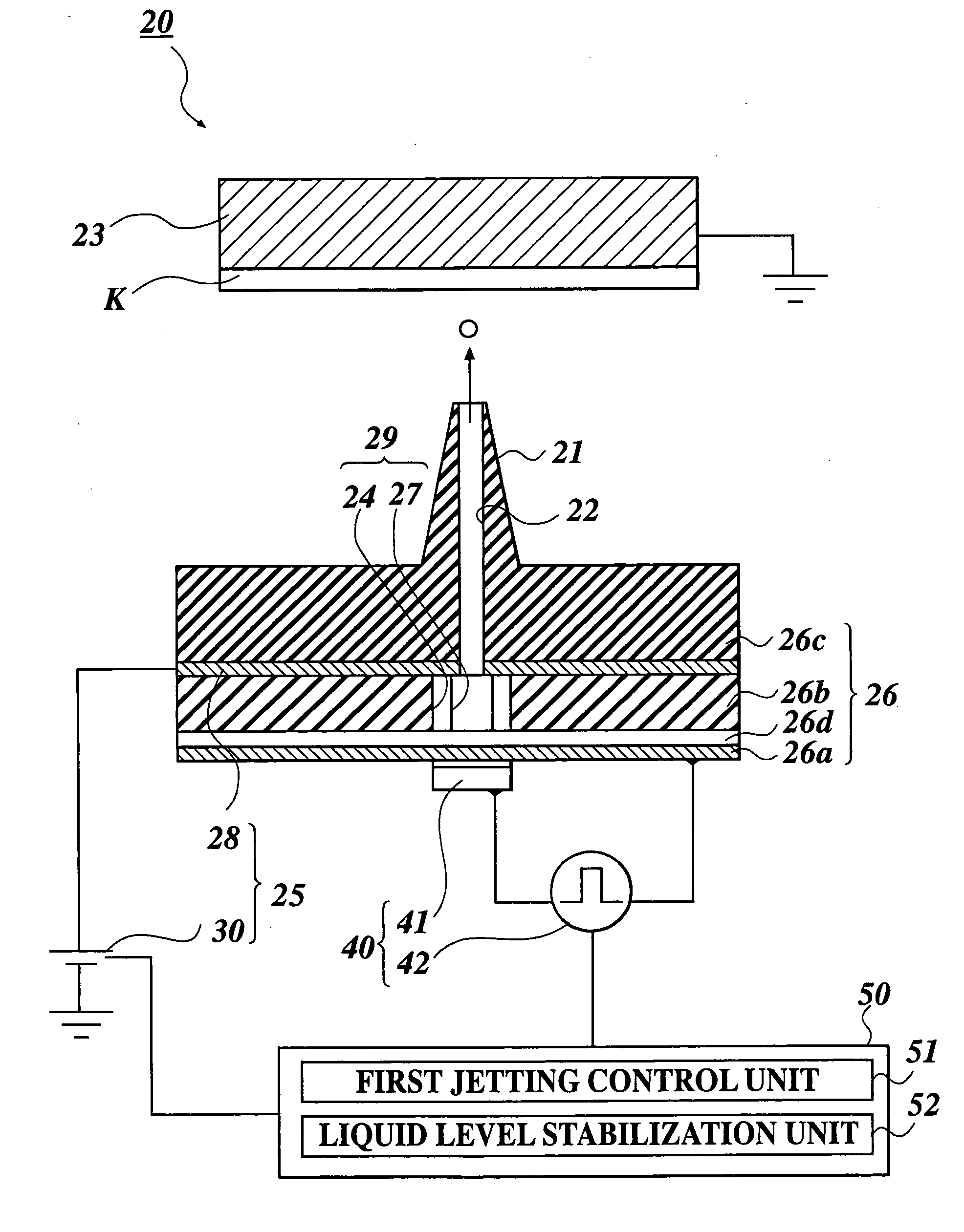
[0101] A liquid jetting apparatus 20 as the first embodiment of the present invention will be described below with reference to FIG. 11 to FIGS. 12. FIG. 11 is a sectional view along a nozzle 21 to be described later of the liquid jetting apparatus 20, and FIGS. 12 are explanation views of a relation between a jetting operation of the liquid solution and a voltage applied to the liquid solution, wherein FIG. 12A shows a state where the jetting is not performed, FIG. 12B shows a state where the jetting is performed, and FIG. 12C shows a state after the jetting.

[0102] The liquid jetting apparatus 20 comprises the nozzle 21 having a super minute diameter for jetting a droplet of chargeable liquid solution from its edge portion, a counter electrode 23 which has a facing surface to face the edge portion of the nozzle 21 and supports a base material K receiving a droplet at the facing surface, a liquid solution supplying section 29 for suppl...

second embodiment

[0147] Next, a liquid jetting apparatus 20A as the second embodiment of the present invention will be explained based on FIG. 13 to FIG. 14C. FIG. 13 is a sectional view of the liquid jetting apparatus 20A, and FIG. 14A, FIG. 14B, and FIG. 14C are explanation views of a relation between a jetting operation of liquid solution and a voltage applied to the liquid solution. FIG. 14A shows a state where the jetting is not performed, FIG. 14B shows a jetting state, and FIG. 14C shows a state after the jetting. In FIG. 13, for the convenience of a description, a state where the edge portion of the nozzle 21 faces upward is illustrated. However, practically, the apparatus is so used that the nozzle 21 faces in a horizontal direction or a lower direction than the horizontal direction, more preferably, the nozzle 21 faces perpendicularly downward.

[0148] In the explanation of the embodiment, the component that is same as that of the liquid jetting apparatus 20 in the first embodiment will be ...


PUM


Abstract

A liquid jetting apparatus (20) to jet a droplet of a charged liquid solution onto a base material, having: a nozzle (21) in which an edge portion thereof is arranged to face the base material K having a receiving surface to receive the jetted droplet, and an inside diameter of the edge portion from which the droplet is jetted is not more than 30 [μm]; a liquid solution supplying section (29) to supply the liquid solution into the nozzle (21); a jetting voltage applying section (25) to apply a jetting voltage to the liquid solution in the nozzle (21); and a convex meniscus forming section (40) to form a state where the liquid solution in the nozzle (21) protrudes from the nozzle edge portion.

Description

FIELD OF THE INVENTION [0001] The present invention relates to a liquid jetting apparatus for jetting liquid to a base material. BACKGROUND ART [0002] As a conventional inkjet recording method, a piezo method for jetting an ink droplet by changing a shape of an ink passage according to vibration of a piezoelectric element, a thermal method for making a heat generator provided in an ink passage heat to generate air bubbles and jetting an ink droplet according to a pressure change by the air bubbles in the ink passage, and an electrostatic sucking method for charging ink in an ink passage to jet an ink droplet by a electrostatic sucking power of the ink are known. [0003] An ink jet printer described in JP-Tokukaihei-11-277747 is cited as a conventional electrostatic sucking type ink jet printer. The ink jet printer comprises a plurality of convex ink guides for jetting ink from an edge portion thereof, a counter electrode which is arranged to face the edge of each ink guide and is gro...

Claims


Application Information

Patent Timeline
Patent Type & Authority Applications(United States)
IPC IPC(8): B05B3/04B41J2/06B41J2/01
CPCB41J2002/14395B41J2/06B41J2/14201B41J2002/14306B41J2002/14411
Inventor NISHI, YASUOHIGUCHI, KAORUMURATA, KAZUHIROYOKOYAMA, HIROSHI
Owner KONICA MINOLTA INC
Why Eureka
Try Eureka