Synchronous permanent magnet planar motor

Active Publication Date: 2006-03-09
TSINGHUA UNIV +1
View PDF11 Cites 25 Cited by
  • Summary
  • Abstract
  • Description
  • Claims
  • Application Information

AI Technical Summary

Benefits of technology

[0012] According to one aspect of the invention, both the number and length of the effective wires in the X-windings and the Y-windings are increased without enlarging the volume of the mover or the stator on which the windings are mounted, and the X-windings and Y-windings overlap in the direction perpendicular to the magnet array, as a result, the electromagnetic force generated by the synchronous permanent magnetic planar motor (“SPMPM”) is increased.
[0013] According to another aspect of the invention, X-windings and Y-windings are mounted on a core made of iron materials, so as to enhance the electro

Problems solved by technology

Conventional SPMPMs have a defect in that the generated electromagnetic forces are relatively small.
Besides, a conventional SPMPM uses the same electromagnetic members, that is, the X-windings and Y-windings in FIG. 3, to gener

Method used


Image

  • Synchronous permanent magnet planar motor
  • Synchronous permanent magnet planar motor
  • Synchronous permanent magnet planar motor

Examples


Embodiment Construction

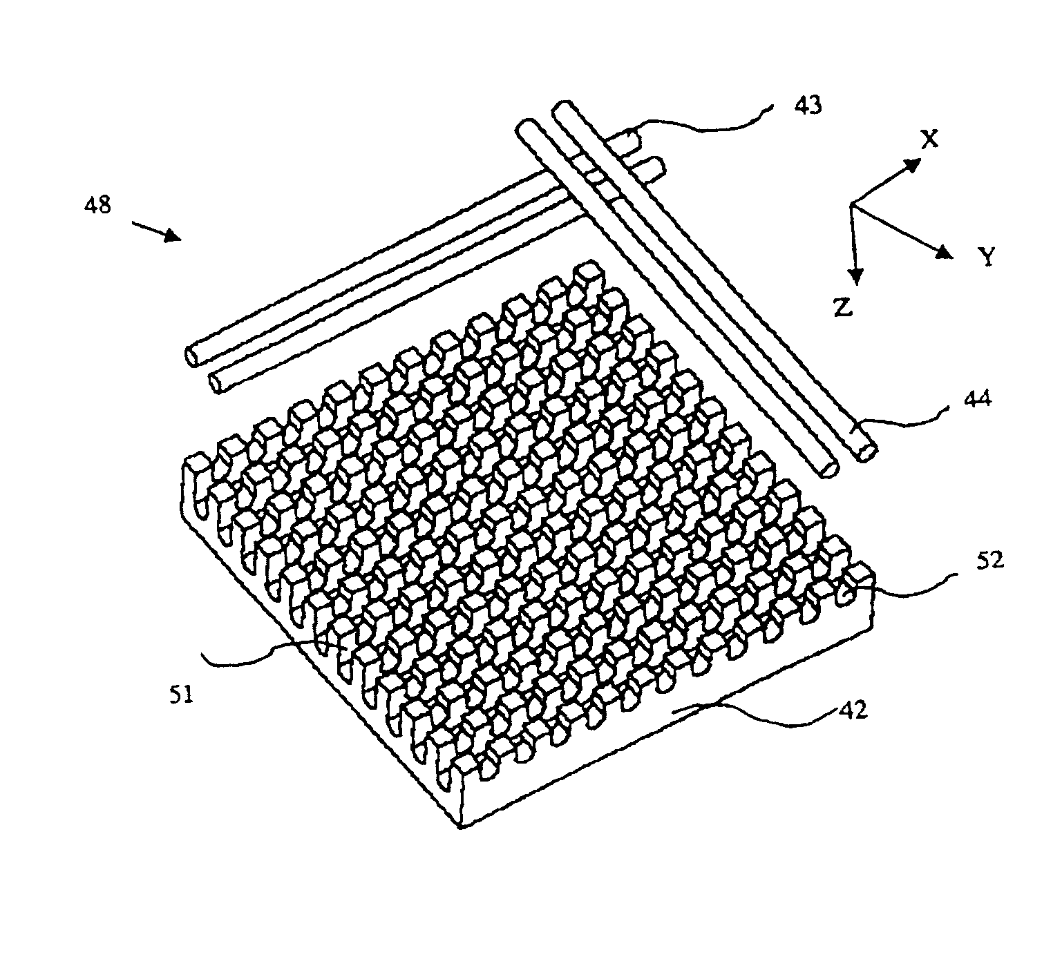
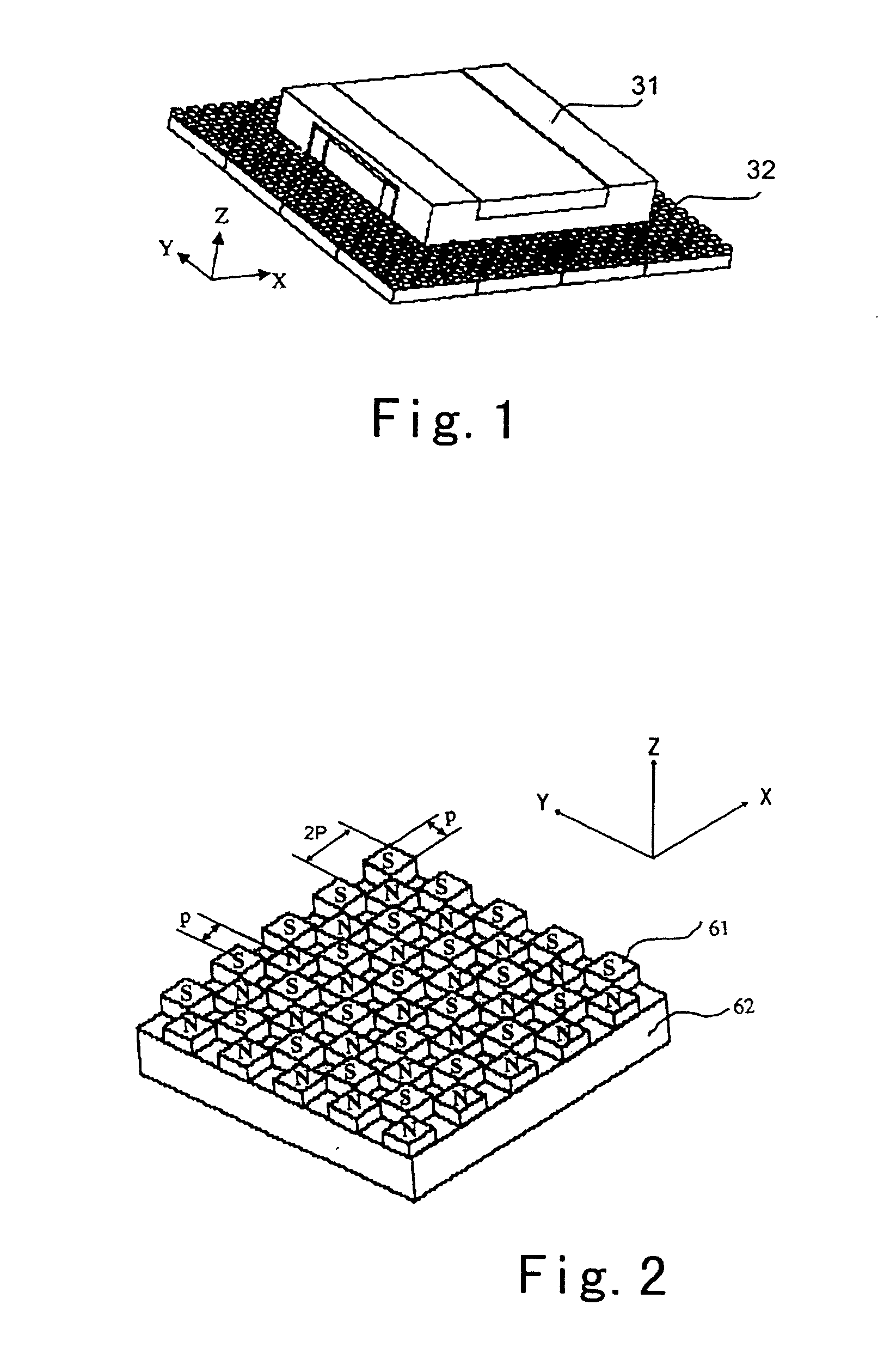
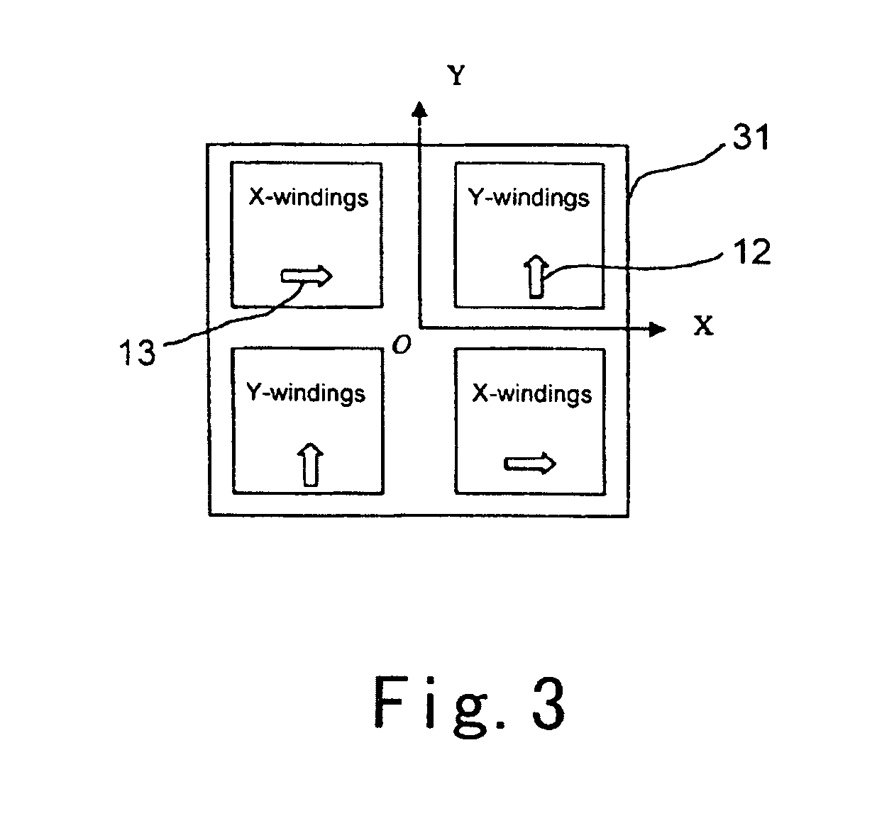
[0023] According to an embodiment of the invention, a magnet array may be fixed on a substrate of a stator in a conventional manner (FIG. 2). X-windings and Y-windings are mount on a mover opposite to the stator. FIG. 5 shows the detailed configuration of a mover according to the invention. The mover comprises a thrust armature 48, two anti-yawing windings 46 and an anti-yawing windings core 47 on which the two anti-yawing windings 46 are mounted. The thrust armature 48 consists of X-windings 44, Y-windings 43 and thrust core 42 on which X-windings and Y-windings are mounted. The thrust armature 48 is attached to the base 45 of the mover via a connecting member 41.

[0024] Both X-windings and Y-windings are disposed in the full area on the bottom surface of the thrust core 42 of the mover, and in the direction normal to the bottom surface of the thrust core 42, i.e., in Z direction, Y-windings and X-windings overlaps. FIG. 6 is a perspective view of the mover along with X-windings 44...


PUM


Abstract

According to the invention, configurations of X-windings and Y-windings in a synchronous permanent planar motor are improved, X-windings and Y-windings overlap in the direction normal to the planar magnet array and distribute on the entire surface of the thrust core, such that effective wires in the X-windings and Y-windings are lengthened and increased in number, therefore the electromagnetic force generated by the SPMPM of this invention is increased correspondingly; X-windings and Y-windings are mounted on a thrust core made of iron material, thus the electromagnetic force is further increased; in addition, two separated anti-yawing member are provided on the mover for counteracting yawing of the mover, accordingly interference between anti-yawing torque and the electromagnetic force for propelling is eliminated.

Description

FIELD OF THE INVENTION [0001] The invention relates to a planar motor, and more particularly, to a synchronous permanent magnet planar motor (SPMPM). BACKGROUND OF THE INVENTION [0002] It's well known that a wire disposed in a magnetic field will create electromagnetic force (also referred to as Lorentz force) when carrying an electric current. In accordance with the Lorentz Law, the electromagnetic force F is given by: F=N L B×I   (1) where N represents the number of wires, L the length of the wire, B the flux density, and I the electric current, the symbol “×” represents vector cross product multiplication. [0003] A synchronous permanent magnet planar motor, which uses electromagnetic force F directly to propel a moving part, has the advantages of simplified structure, light weight and high positioning precision. [0004] The previously proposed Synchronous permanent magnet planar motors comprise a planar magnet array having a plurality of magnets with magnetic fields of alternatin...

Claims


Application Information

Patent Timeline
IPC IPC(8): H02K41/00H02K41/03
CPCH02K2201/18H02K41/03
Inventor WANG, JINSONGZHU, YUCAO, JIAYONGYIN, WENSHENGDUAN, GUANGHONG
Owner TSINGHUA UNIV
Why Eureka
Try Eureka