Displacement encoder, device comprising such an encoder and method of manufacturing such an encoder

a technology of displacement encoder and encoder, which is applied in the direction of measuring devices, devices using electric/magnetic means, instruments, etc., can solve the problems of ferrite filled elastomer too fragile and crumbly for certain applications, and the magnetic field created by ferrite filled elastomer does not reach a sufficient intensity for certain applications

Inactive Publication Date: 2006-03-09
HUTCHINSON SA
View PDF7 Cites 10 Cited by
  • Summary
  • Abstract
  • Description
  • Claims
  • Application Information

AI Technical Summary

Benefits of technology

[0007] The elastomer layer thus produced makes it possible to ensure a robust mechanical bond, in particular in the presence of vibrations and thermal expansions, between the magnet and the sleeve, whether the latter is made of plastic or metal, due to the chemical bond created between these parts by adherization. Moreover, the overmoulding creates a layer which isolates the permanent magnet from the external environment.
[0009] The fact that the permanent magnet or magnets are protected by an elastomer layer allows the use of standard magnets which do not have particularly high resistance to chemical oxidation specifications, such as for example ferrite-based magnets, which makes it possible to limit the cost of the encoder.
[0011] the permanent magnet has a rear face disposed at least partially against the sleeve, a front face opposite to the rear face and side faces connecting said rear and front faces, the elastomer layer covering the side faces having a thickness at least five times greater than the thickness of the elastomer layer covering the front face, which makes it possible to produce a good compromise between the protection of the magnet, the dimensions of the encoder and its mechanical strength;
[0014] the permanent magnet is a plastomagnet and preferably a plastomagnet of samarium-cobalt type which has the advantage of retaining a strong magnetic field when the temperature rises;
[0020] This device can furthermore comprise a casing filled with liquid, or with grease, in which the rotary shaft penetrates, and an annular lip, made in one piece from the material of the elastomer layer, which is in sliding contact with the casing and ensures the fluid-tightness between said shaft and said casing.

Problems solved by technology

However, the magnetic field created by the ferrite filled elastomer does not reach a sufficient intensity for certain applications, in particular when the air-gap between the encoding zone reaches a value that is too large because of the space available for the magnetic field sensor or because of the variations in the air-gap during the functioning of the device.
However, the densities of magnetic particles henceforth achieved make the ferrite filled elastomer too fragile and crumbly for certain applications.

Method used


Image

  • Displacement encoder, device comprising such an encoder and method of manufacturing such an encoder
  • Displacement encoder, device comprising such an encoder and method of manufacturing such an encoder
  • Displacement encoder, device comprising such an encoder and method of manufacturing such an encoder

Examples


second embodiment

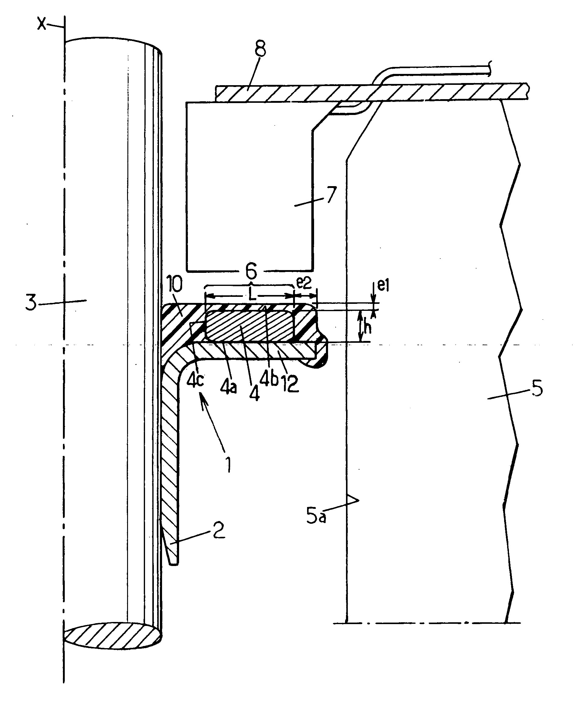
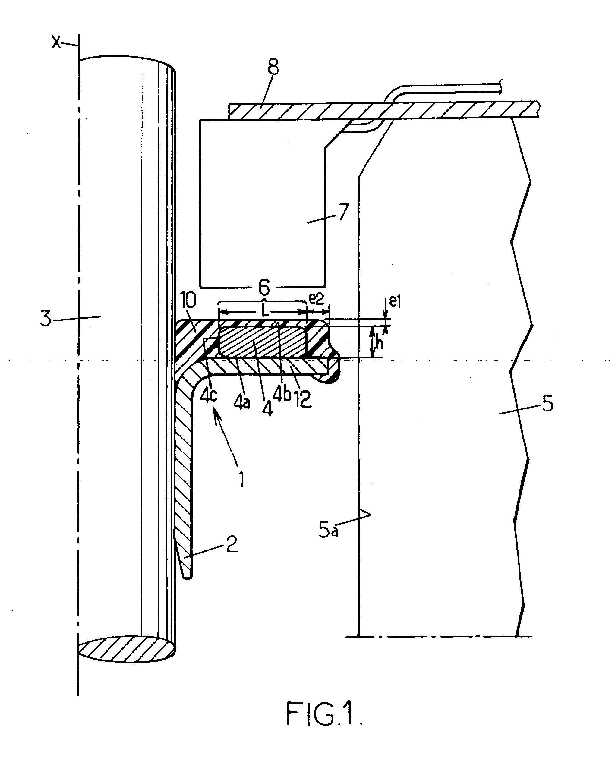
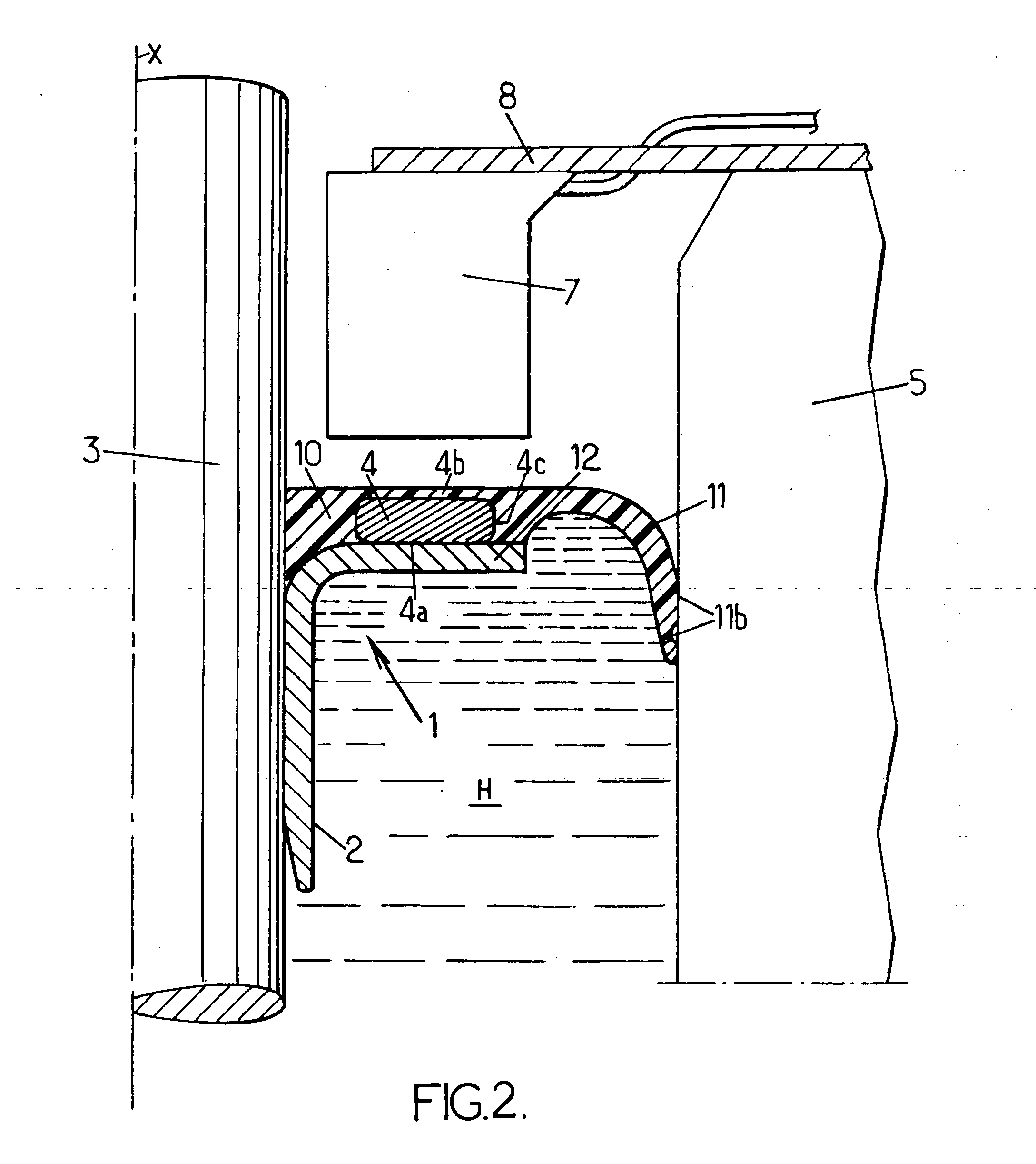
[0053] The angular encoder 1 thus produced fulfils a dynamic fluid-tightness sealing function in addition to its encoding function. the angular encoder is therefore more particularly intended for a device such as an engine or a gear box in which the casing 5 filled with a liquid H, possibly under pressure, is traversed by a shaft 3, in order to provide fluid-tightness between the shaft and the casing.

[0054] In the embodiment shown in FIG. 2, the base of the lip 11 extends substantially in the extension of the layer 10 and is curved, in the configuration shown, during the positioning of the angular encoder on the shaft 3. The end 11a of the lip can comprise on its surface in contact with the fixed casing 5 grooves 11b which improve the dynamic fluid-tightness between the lip and the radial surface 5a of the casing facing the shaft 3.

[0055] It is of course possible for the lip 11 to have a more complex geometric configuration in order to be adapted to the configuration of the surface...

third embodiment

[0057] In this third embodiment, the encoding zone 6 extends longitudinally and is oriented radially towards the sensor 7. The encoding zone 6 is formed by a cylindrical tubular magnet 4 which closely surrounds a cylindrical wall of the sleeve 2 coaxial with the longitudinal axis X, such that the encoding zone is annular and concentric with the shaft 3. The use of a one-piece annular magnet makes it possible to obtain a high accuracy of positioning of the polarized marks, but the use of several magnets is also possible.

[0058] The protective layer 10 covers the magnet 4, but also the entire external surface of the sleeve 2 and thus protects the whole of the encoder against mechanical or chemical attacks coming from outside of the casing 5.

[0059] The sleeve 2 has a U-shaped cross-section, a first branch 20 of the U clamping the shaft 3, a second branch 21 supporting the magnet 4 and the base 9 of the U making it possible to take up a part of the clearance between the shaft 3 and the ...


PUM


Abstract

Displacement encoder for a moving shaft, having a sleeve intended to be clamped on the shaft and an encoding zone having polarized magnetic mark. The encoding zone has permanent magnet disposed against the sleeve and a layer of elastomer is overmolded and adherized on the magnet and on the sleeve.

Description

FIELD OF THE INVENTION [0001] The present invention relates to a displacement encoder for a moving shaft and, more particularly, to an encoder comprising a sleeve intended to be clamped on the shaft and an encoding zone having at least one polarized magnetic mark. [0002] In many applications, in particular for wheel shafts, output shafts of gearboxes or crankshafts of internal combustion engines, the shafts are equipped with angular or linear displacement encoding devices in order to know their instantaneous speed and / or their position and / or their direction of displacement. BACKGROUND OF THE INVENTION [0003] The encoding function can be carried out by one or more polarized magnetic marks which form an encoding zone whose displacement is detected by a magnetic field detector disposed facing this encoding zone. For this type of encoder, it is known, in particular from the document FR-A 2 777 060, to produce the mark or marks of the encoding zone using a ferrite filled elastomer layer...

Claims


Application Information

Patent Timeline
Patent Type & Authority Applications(United States)
IPC IPC(8): G01P3/48G01D5/14G01P3/487
CPCG01P3/487G01P3/443G01D2205/80
Inventor FAYAUD, PATRICKGUERBE, LAURENT
Owner HUTCHINSON SA
Why Eureka
Try Eureka